Publication 1763-RM001C-EN-P - October 2009
446 LCD - LCD Information
sensors, timer “done bits”, message from another controller, etc.), or
based on a scheduled action (using the embedded real time clock, or free
running timers).
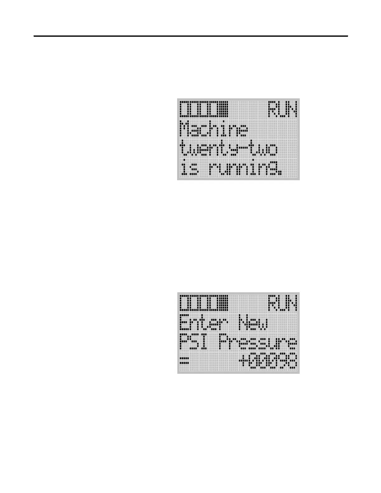
The second mode of operation again allows for output from the ladder
logic to the display, but adds input from the operator back to the
controller (hereafter called “Display With Input mode”). Up to two lines of
up to 12 characters each can still be sent to the LCD for display, but the
third line, in this mode, is used to obtain numeric input from the user. Bit,
integer, or long integer file types can be used to provide this input.
The user can select “User Display” from the LCD menu. The User Display
screen will show the specified output data when the LCD Instruction is
energized.
If “DISPLAY WITH INPUT” is set to “YES”, the user can enter input using
the LCD keypad to enter Bit, Integer, or Long Integer data.
LCD Function File
Within the RSLogix 500 Function File Folder, you see a LCD Function File.
This file provides access to LCD and Trimpot configuration data, and also
allows the control program access to all information pertaining to LCD
screen, keypad, Trimpot.
efesotomasyon.com - Allen Bradley,Rockwell,plc,servo,drive

 Loading...


