Publication 1763-RM001C-EN-P - October 2009
542 Knowledgebase Quick Starts
# 17446 “Quick Start”
Pulse Width Modulation
(PWM)
NOTE: The PWM function is only available when using the BBB models
of the MicroLogix 1100.
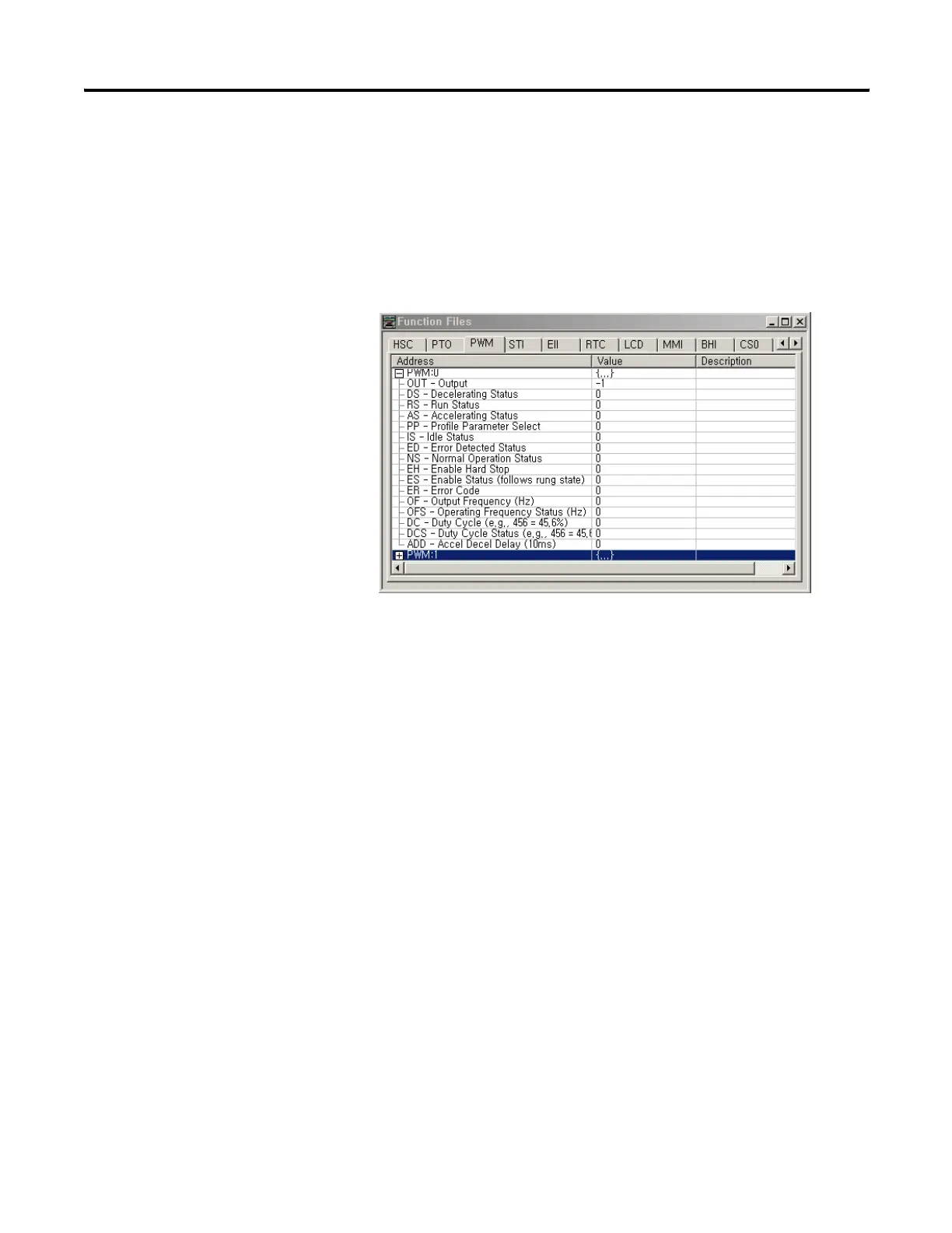
Locate the Function Files under Controller in RSLOGIX 500 v7.00.00 or
later and select the PWM tab, then select the [+] next to PWM:0 (See
Below).
Enter the following parameters as the “Minimum Configuration” required
for the PWM to generate a waveform at the specified frequency.
PWM:0.OUT Select Destination Output for pulses: Output O:0/2 or O:0/3
PWM:0.OFS Output Frequency - Frequency of the PWM: 0 to 20,000 Hz
PWM:0.DC PWM Duty Cycle - Controls the output signal of the PWM: 1 to 1000
DC = 1000 100% Output ON (Constant no waveform)
DC = 0750 075% Output ON 025% Output OFF
DC = 0500 050% Output ON 050% Output OFF
DC = 0250 025% Output ON 075% Output OFF
DC = 0000 000% Output OFF (Constant no Waveform)
efesotomasyon.com - Allen Bradley,Rockwell,plc,servo,drive

 Loading...


