Publication 1763-RM001C-EN-P - October 2009
40 Controller Memory and File Types
Data Files
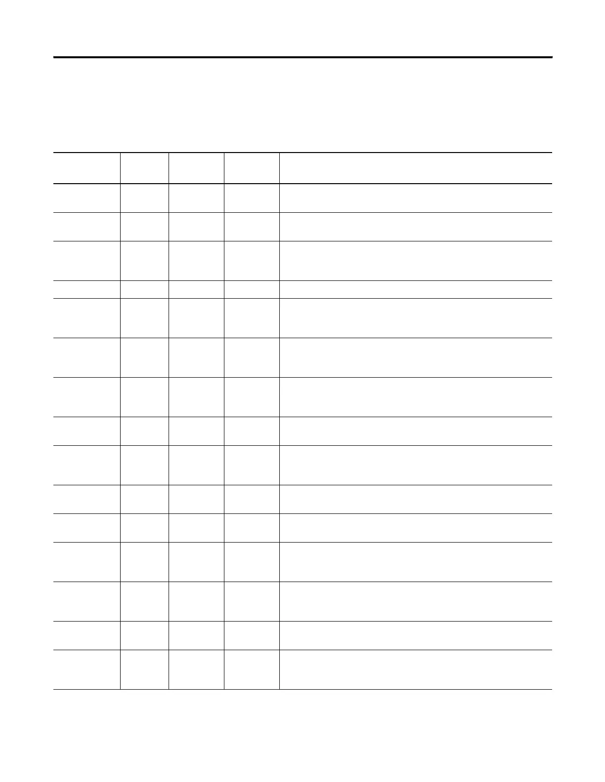
Data files store numeric information, including I/O, status, and other data
associated with the instructions used in ladder subroutines. The data file
types are:
File Name File
Identifier
File
Number
(2)
Words per
Element
File Description
Output File O 0 1 The Output File stores the values that are written to the physical outputs
during the Output Scan.
Input File I 1 1 The Input File stores the values that are read from the physical inputs
during the Input Scan.
Status File S 2 1 The contents of the Status File are determined by the functions which
utilize the Status File. See System Status File on page 465 for a detailed
description.
Bit File B 3, 9 to 255 1 The Bit File is a general purpose file typically used for bit logic.
Timer File T 4, 9 to 255 3 The Timer File is used for maintaining timing information for ladder logic
timing instructions. See Timer and Counter Instructions on page 167 for
instruction information.
Counter File C 5, 9 to 255 3 The Counter File is used for maintaining counting information for ladder
logic counting instructions. See Timer and Counter Instructions on page
167 for instruction information.
Control File R 6, 9 to 255 3 The Control Data file is used for maintaining length and position
information for various ladder logic instructions. See Control Data File on
page 313 for more information.
Integer File N 7, 9 to 255 1 The Integer File is a general purpose file consisting of 16-bit, signed
integer data words.
Floating Point
File
F 8, 9 to 255 2 The Floating Point File is a general purpose file consisting of 32-bit
IEEE-754 floating point data elements. See Using the Floating Point (F)
Data File on page 190 for more information.
String File ST 9 to 255 42 The String File is a file that stores ASCII characters. See String (ST) Data
File on page 312 for more information.
Long Word File L 9 to 255 2 The Long Word File is a general purpose file consisting of 32-bit, signed
integer data words.
Message File MG 9 to 255 25 The Message File is associated with the MSG instruction. See
Communications Instructions on page 341 for information on the MSG
instruction.
Programmable
Limit Switch File
PLS 9 to 255 6 The Programmable Limit Switch (PLS) File allows you to configure the
High-Speed Counter to operate as a PLS or rotary cam switch. See
Programmable Limit Switch (PLS) File on page 120 for information.
PID File PD 9 to 255 23 The PID File is associated with the PID instruction. See Process Control
Instruction on page 279 for more information.
Routing
Information File
RI 9 to 255 20 The Routing Information File is associated with the MSG instruction. See
Communications Instructions on page 341 for information on the MSG
instruction.
efesotomasyon.com - Allen Bradley,Rockwell,plc,servo,drive
 Loading...


