Publication 1763-RM001C-EN-P - October 2009
36 Controller Memory and File Types
Controller Memory
File Structure
MicroLogix 1100 user memory is comprised of Data Files, Function Files,
and Program Files.
TIP
The file types shown below for data files 3 through 8 are the default file types for those
file numbers and cannot be changed. Data files 9 through 255 can be added to your
program to operate as bit, timer, counter, or other files shown below.
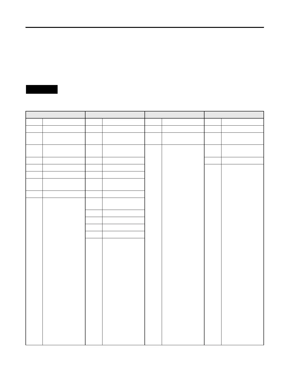
Data Files Function Files Program Files Specialty Files
0 Output File HSC High Speed Counter 0 System File 0 0 Data Log Queue 0
1 Input File PTO Pulse Train Output 1 System File 1 1 Data Log Queue 1
2 Status File PWM Pulse Width
Modulation
2 Program File 2 2 to 255 Data Log Queues 2 to
255
3 Bit File STI Selectable Timed
Interrupt
3 to 255 Program Files 3 to 255 0 Recipe File 0
4 Timer File EII Event Input Interrupt 1 Recipe File 1
5 Counter File RTC Real Time Clock 2 to 255 Recipe Files 2 to 255
6 Control File
7 Integer File MMI Memory Module
Information
8 Floating Point File
9 to 255 (B) Bit
(T) Timer
(C) Counter
(R) Control
(N) Integer
(F) Floating Point
(ST) String
(L) Long Word
(MG) Message
(PD) PID
(PLS) Programmable
Limit Switch
(RI) Routing Information
(RIX) Extended Routing
Information (OS Series
B FRN 4 or later)
BHI Base Hardware
Information
CS Communications Status
IOS I/O Status
DLS Data Log Status
LCD LCD
ES Ethernet Status
efesotomasyon.com - Allen Bradley,Rockwell,plc,servo,drive

 Loading...


