Programming and Parameters 3-53
Advance Display Group (continued)
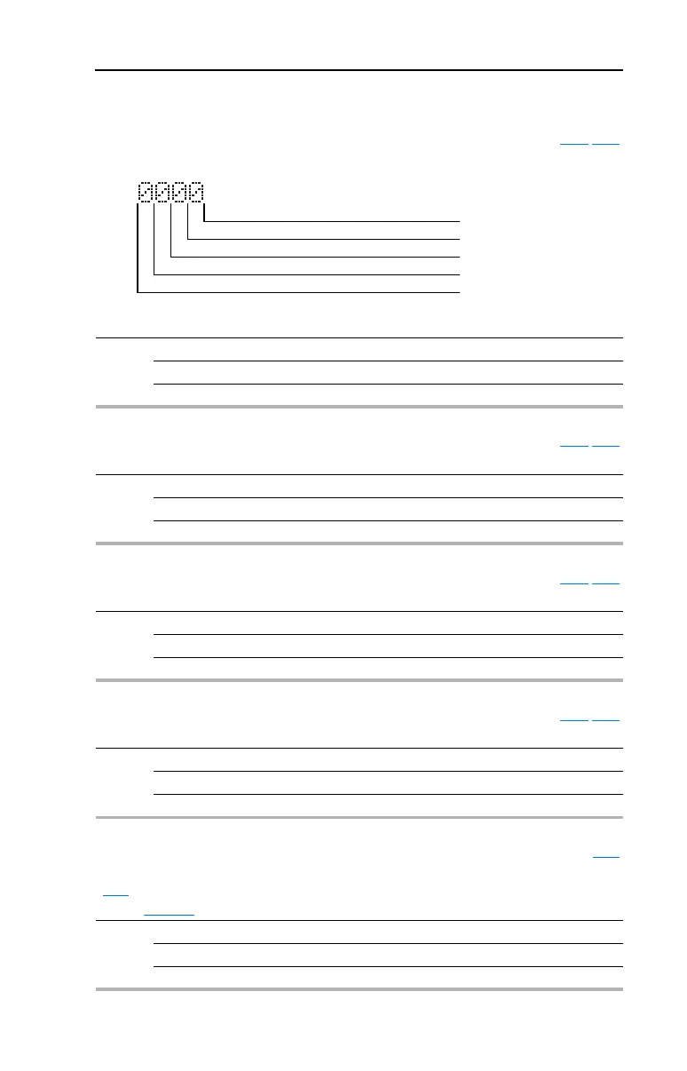
d303 [Comm Status] Related Parameter(s): C102-C103
Status of the communications ports.
Values Default: Read Only
Min/Max: 0/1111
Display: 1
1 = Condition True, 0 = Condition False
Received Good Message Packet Digit 0
Transmitting Message Digit 1
DSI Peripheral Connected Digit 2
Received Bad Message Packet Digit 3
d304 [PID Setpnt Displ] Related Parameter(s): C102-C103
Displays the active PID Setpoint value.
Values Default: 0.0%
Min/Max: 0.0/100.0%
Display: 0.1%
d305 [Analog In 1] Related Parameter(s): C102-C103
Displays the status of Analog Input 1.
Values Default: 0.0%
Min/Max: 0.0/120.0%
Display: 0.1%
d306 [Analog In 2] Related Parameter(s): C102-C103
Displays the status of Analog Input 2.
Values Default: 0.0%
Min/Max: 0.0/120.0%
Display: 0.1%
d307 [Fault 1 Code] Related Parameter(s): A197
A code that represents a drive fault. The codes will appear in these parameters in the order they occur
(b007
[Fault 1 Code] = the most recent fault). Repetitive faults will only be recorded once.
Refer to Chapter
4 for fault code descriptions.
Values Default: Read Only
Min/Max: 0/122
Display: 1

 Loading...


