D-12 Application Notes
Example 1
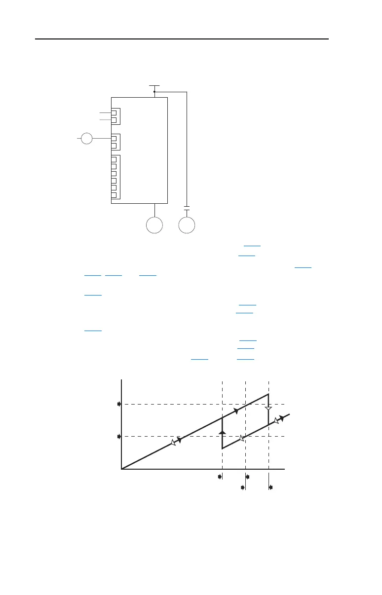
One External Motor without AutoSwap
• Auxiliary Motor Control is enabled via Parameter R239 [Aux Motor Mode].
• Number of auxiliary motors is set via Parameter R240
[Aux Motor Qty].
• Relays are configured for Auxiliary Motor Control via parameters T055
,
T060
, R222, and R225.
• The frequency of Motor #1 that Motor #2 turns on at is set via Parameter
R241
[Aux 1 Start Freq].
• The time that Motor #1 is above the value set by R241
[Aux 1 Start Freq]
before turning on Motor #2 is set via Parameter R250 [Aux Start Delay].
• The frequency of Motor #1 that Motor #2 turns off at is set via Parameter
R242
[Aux 1 Stop Freq].
• The time that Motor #1 is below the value set by R242
[Aux 1 Stop Freq]
before turning off Motor #2 is set via Parameter R251 [Aux Stop Delay].
• PID setup is done via Parameters A150
through A159. See Appendix D for
additional information.
Important: If using auxiliary motor control, ensure that wiring and parameter
configuration are correct before wiring contactor outputs. All relays
on the Auxiliary Relay Card will energize on power-up by default.
Failure to verify proper wiring and parameter configuration can result
in improper motor operation or drive damage.
PID
Reference
Feedback
Drive Relays
Auxiliary Relay Card
M2L
PowerFlex 400
Three-Phase Power
M2L
M1 M2
Frequency
R241 [Aux 1 Start Freq]
R251 [Aux Stop Delay]
R250 [Aux Start Delay]
R242 [Aux 1 Stop Freq]
Time

 Loading...


