Installation/Wiring 1-7
Input Power Conditioning
The drive is suitable for direct connection to input power within the rated
voltage of the drive (see Appendix
A). Listed in Table 1.A are certain
input power conditions which may cause component damage or
reduction in product life. If any of the conditions exist, as described in
Table 1.A
, install one of the devices listed under the heading Corrective
Action on the line side of the drive.
Important: Only one device per branch circuit is required. The device
should be mounted closest to the branch and sized to handle
the total current of the branch circuit.
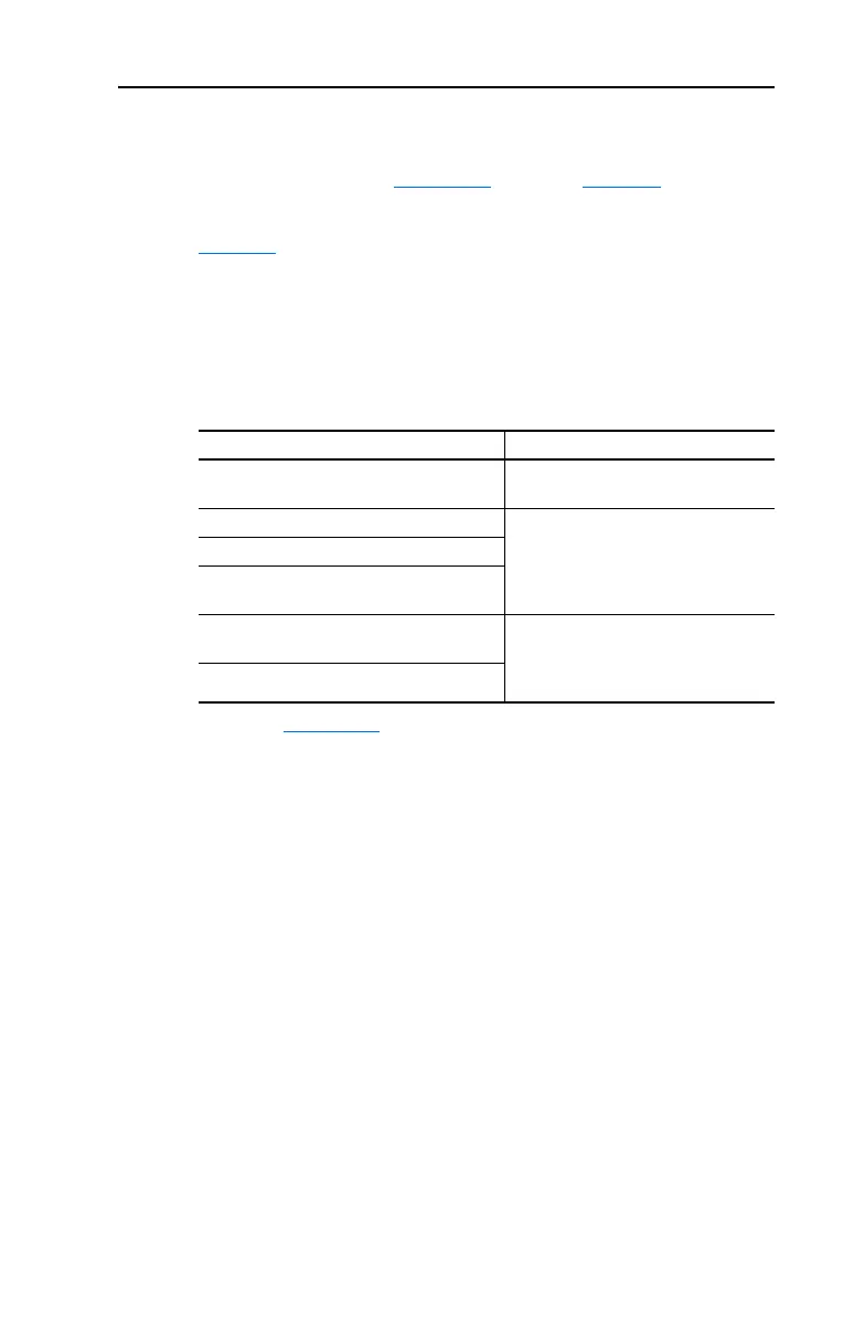
Table 1.A Input Power Conditions
Input Power Condition Corrective Action
Low Line Impedance (less than 1% line
reactance)
• Install Line Reactor
(1)
• or Isolation Transformer
(1)
Refer to Appendix B for accessory ordering information.
Line has power factor correction capacitors • Install Line Reactor
(1)
• or Isolation Transformer
Line has frequent power interruptions
Line has intermittent noise spikes in excess of
6000V (lightning)
Phase to ground voltage exceeds 125% of
normal line to line voltage
• Remove MOV jumper to ground
(Frame C, E & F drives only)
• or Install Isolation Transformer with
grounded secondary if necessary
Ungrounded distribution system

 Loading...


