1-12 Installation/Wiring
Shielded cable may also help reduce shaft voltage and induced bearing
currents for some applications. In addition, the increased impedance of
shielded cable may help extend the distance that the motor can be
located from the drive without the addition of motor protective devices
such as terminator networks. Refer to Reflected Wave in “Wiring and
Grounding Guidelines for PWM AC Drives,” publication
DRIVES-IN001A-EN-P.
Consideration should be given to all of the general specifications
dictated by the environment of the installation, including temperature,
flexibility, moisture characteristics and chemical resistance. In addition,
a braided shield should be included and be specified by the cable
manufacturer as having coverage of at least 75%. An additional foil
shield can greatly improve noise containment.
A good example of recommended cable is Belden® 295xx (xx
determines gauge). This cable has four (4) XLPE insulated conductors
with a 100% coverage foil and an 85% coverage copper braided shield
(with drain wire) surrounded by a PVC jacket.
Other types of shielded cable are available, but the selection of these
types may limit the allowable cable length. Particularly, some of the
newer cables twist 4 conductors of THHN wire and wrap them tightly
with a foil shield. This construction can greatly increase the cable
charging current required and reduce the overall drive performance.
Unless specified in the individual distance tables as tested with the drive,
these cables are not recommended and their performance against the lead
length limits supplied is not known.
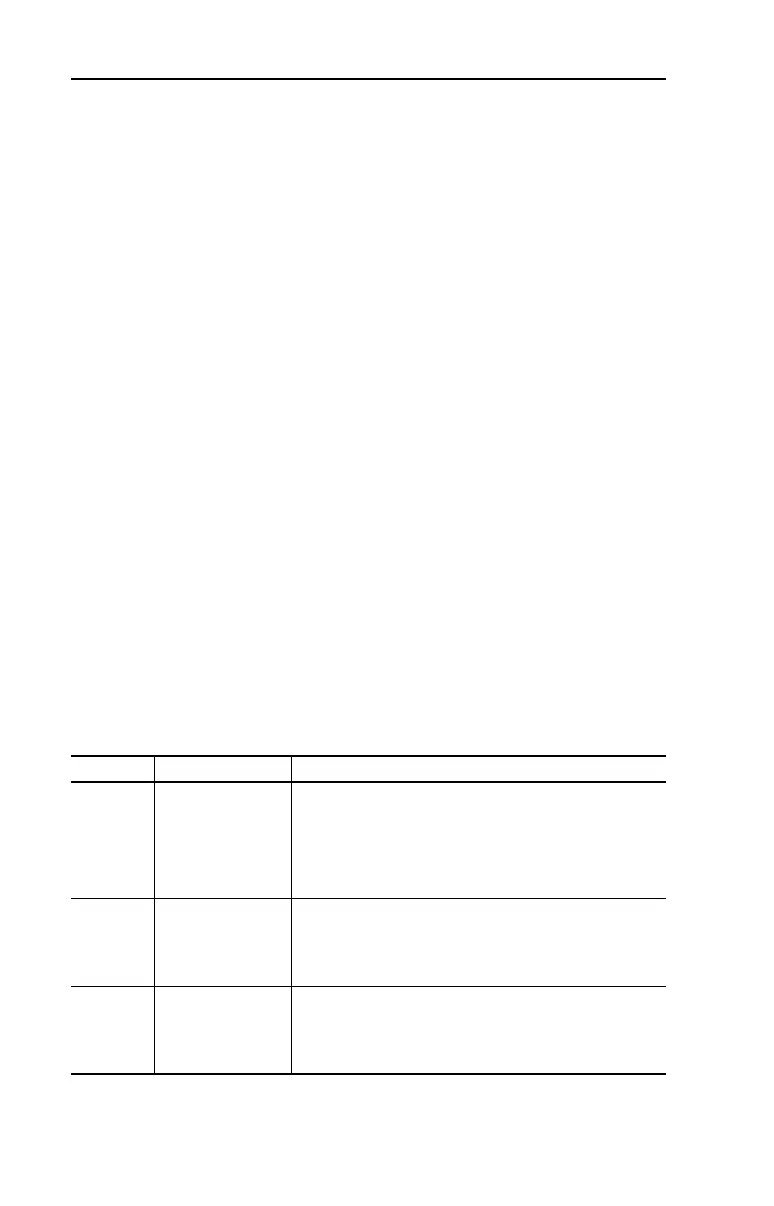
Recommended Shielded Wire
Location Rating/Type Description
Standard
(Option 1)
600V, 90°C (194°F)
XHHW2/RHW-2
Anixter
B209500-B209507,
Belden 29501-29507,
or equivalent
• Four tinned copper conductors with XLPE insulation.
• Copper braid/aluminum foil combination shield and tinned
copper drain wire.
• PVC jacket.
Standard
(Option 2)
Tray rated 600V, 90°C
(194°F) RHH/RHW-2
Anixter OLF-7xxxxx or
equivalent
• Three tinned copper conductors with XLPE insulation.
• 5 mil single helical copper tape (25% overlap min.) with three
bare copper grounds in contact with shield.
• PVC jacket.
Class I & II;
Division I & II
Tray rated 600V, 90°C
(194°F) RHH/RHW-2
Anixter 7V-7xxxx-3G
or equivalent
• Three bare copper conductors with XLPE insulation and
impervious corrugated continuously welded aluminum armor.
• Black sunlight resistant PVC jacket overall.
• Three copper grounds on #10 AWG and smaller.

 Loading...


