Installation/Wiring 1-21
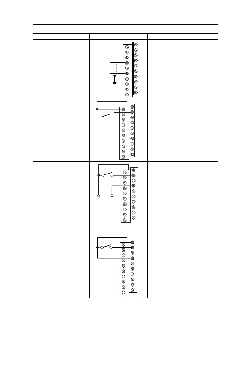
Analog Output
Unipolar, 4-20 mA Output
• 525 Ohm Maximum
DIP Switch
AO1 = 20MA
Parameters
T082 [Analog Out1 Sel] = 14 through 20
Scaling
T083 [Analog Out1 High]
T084 [Analog Out1 Setpt]
2 Wire Control
Sourcing (SRC),
Internal Supply,
Non-Reversing
• Input must be active for the
drive to run.
• When input is opened, the
drive will stop as specified by
P037 [Stop Mode].
• Drive will not run if I/O
Terminal 01 is open. Drive will
coast to stop if opened while
running.
DIP Switch
SNK/SRC = SRC
Parameters
P036 [Start Source] = 2, 3, 4
P037 [Stop Mode] = 0 through 7
2 Wire Control
Sourcing (SRC),
External Supply,
Non-Reversing
• Input must be active for the
drive to run.
• When input is opened, the
drive will stop as specified by
P037 [Stop Mode].
• User supplied 24V DC power
source must be used.
• Each digital input draws 6 mA.
• Drive will not run if I/O
Terminal 01 is open. Drive will
coast to stop if opened while
running.
DIP Switch
SNK/SRC = SRC
Parameters
P036 [Start Source] = 2, 3, 4
P037 [Stop Mode] = 0 through 7
2 Wire Control
Sinking (SNK),
Internal Supply,
Non-Reversing
• Input must be active for the
drive to run.
• When input is opened, the
drive will stop as specified by
P037 [Stop Mode].
• Drive will not run if I/O
Terminal 01 is open. Drive will
coast to stop if opened while
running.
DIP Switch
SNK/SRC = SNK
Parameters
P036 [Start Source] = 2, 3, 4
P037 [Stop Mode] = 0 through 7
Input/Output Connection Example Required Settings
14
16
Common
+
11
01
02
Stop-Run
+24V Common
01
02
04
Stop-Run
01
02
04
Stop-Run

 Loading...


