Chapter 2: Installation
2X Series Installation Manual 21
The inserts are numbered 1, 2, 3, and 4, and are inserted at the location
indicated (with the printed area facing the front of the control panel).
For evacuation panels, remember to add descriptions for any output groups
assigned to the programmable buttons to insert 3.
Note: Different versions of insert 3 are provided for fire panels and for evacuation
panels, and each is marked with the corresponding control panel product code.
Be sure to use the correct version of the insert for your product.
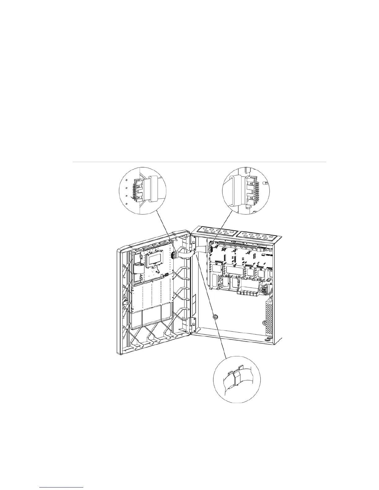
Connecting the user interface cable
Connect the user interface cable as shown below.
Figure 9: Connecting the user interface cable

 Loading...