7. Communicator touch panel
A Touch s creen
B
Communication panel
C
Knob to operate central swivel clamp
D
Base of swivel arm
E
Power input 12 VDC, 1.5A
F
RS232 port (sub-D)
G Ethernet port (RJ45)
CAUTION: For more information about the use of the Communicator Touch Panel, consult its user guide.
7.2 Installing the touch panel interface
Necessary tools
• 17 mm wr ench.
• 10 mm wr ench.
How to install the touch pa nel interface upon the DP2K C-series project
or?
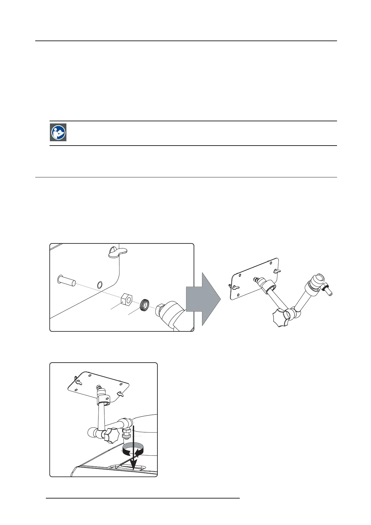
1. Assemble the mounting plate and the swivel arm together as illustrated. First place the nut (N) up on the rod of the mounting
plate, then add the lock washer (L), then fasten the mounting plate and the swiv el arm together. When the arm is mounted, turn
nut (N) against the arm to s ecure the pos ition.
N
L
Image 7-3
Assemble swivel arm
2. Slide a washer (M) over the base of the swivel arm and Insert the base of the swivel arm into the mounting hole at the top of the
DP2K C-series pr ojectoras illustrated.
M
Image 7-4
Mount swivel arm
54 R5905050 DP2K C-SERIES 10/07/2012
 Loading...


