38
7217395.01 - en
INSTRUCTIONS PERTAINING TO THE INSTALLER
A Qualied Service Engineer may adapt this boiler to operate with natural gas (G. 20) or with liquid gas (G. 31).
The procedure for calibrating the pressure regulator may vary according to the type of gas valve tted (HONEY WELL or
SIT; see gure 8).
Carry out the following ope rations in the given sequence:
A) substitute the main burner injectors;
B) change the modulator voltage;
C) proceed with a new max. and min. setting of the pressure adjusting device.
A) Substitute the main burner injectors
• carefully pull the main burner off its seat;
• substitute the main burner injectors and make sure you tighten them to avoid leakage. The nozzle diameters are spe-
cied in table 1.
B) Change the modulator voltage
• setting F02 parameter according to the gas used as described in section 19.
C) Pressure adjusting device setting
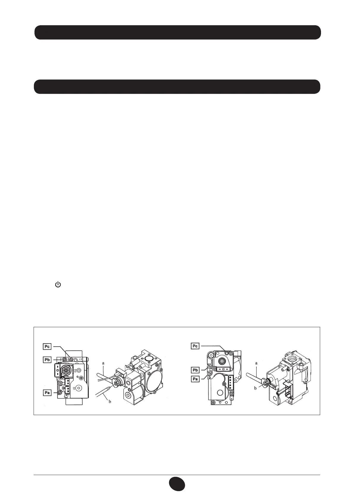
• connect the positive pressure test point of a differential (possibly water-operated) manometer to the gas valve pressure
test point (Pb) (Figure 8).
C1) Adjustment to nominal heat output
• open the gas tap;
• press button (gure 1) and set the boiler in winter mode (section 3.2);
• open a hot water tap to reach a minimum 10 l/min ow rate or ensure that maximum heating requirements are set;
• remove the modulator cover;
• adjust the tube brass screw (a) Fig. 8 to obtain the pressure settings shown in table 1;
• check that boiler feeding dynamic pressure, as measured at the inlet gas valve pressure test point (Pa) (Figure 8) is
correct (37 mbar for propane gas G.31, 20 mbar for natural gas G20);
17. GAS CHANGE MODALITIES
16. FITTING A ROOM THERMOSTAT
To connect the room thermostat to the boiler terminal block, proceed as follows:
• reach the power supply terminal block (gure 7);
• connect the room thermostat to the terminals (1) - (2) and remove the jumper.
Figure 8
SIT valve mod. SIGMA 845 Honeywell valve mod. VK 4105 M
0904_0701
 Loading...