Digital inputs and outputs
Function description 25
Version: 1.5
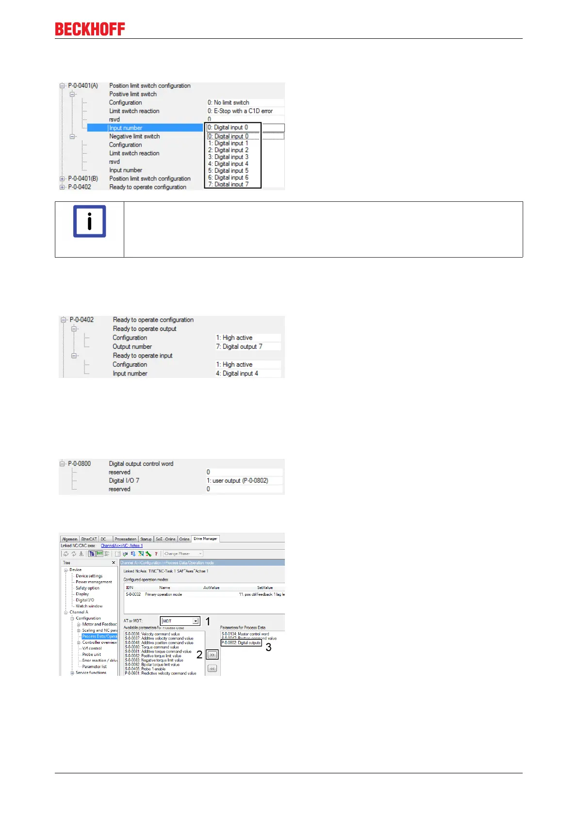
Input number
Under this setting in parameter P-0-0401 you can specify which
digital input is to be configured with the function „Position limit
switch“. You can assign the function to one of eight digital inputs
(0-7).
Note
Configuration of the positive and negative limit switch
The positive and negative limit switch can be configured in parameter P-0-0401. The se-
lectable settings are identical for both limit switch versions and are described in this chapter
for the positive limit switch only.
6.4 Ready to operate
In the AX5000 configuration this device can be
integrated in the ready-chain of the machine. This
function requires a digital input and a digital output.
Activation of this function and allocation to the
respective input and output is realized in parameter
P-0-0402. Since only digital input no. 7 can optionally
be configured as output, only digital output no. 7 is
offered as output number.
6.5 Digital output control word
Default value: 0 no output
Digital output 7 can be configured as „user output“ at
the AX5000 servo drive for signal output from the
PLC.
1: user output (P-0-0802)
Digital output 7 can be controlled via parameter
P-0-0802.
The parameter P-0-0802 (3) can now be mapped in
the MasterDataTelegram (1) process data of the
AX5000 servo drive and linked to a PLC variable.
Proceed as follows:
• Adding parameters from „Available parameters
for process data“ to the „Parameters for
process data“ via the button (2).
Bit 7 of this variable controls the state of digital output
7.

 Loading...


