Comissioning a Generic Encoder with BISS-C Interface
Function description30
Version: 1.5
7.7.3 Process Channel
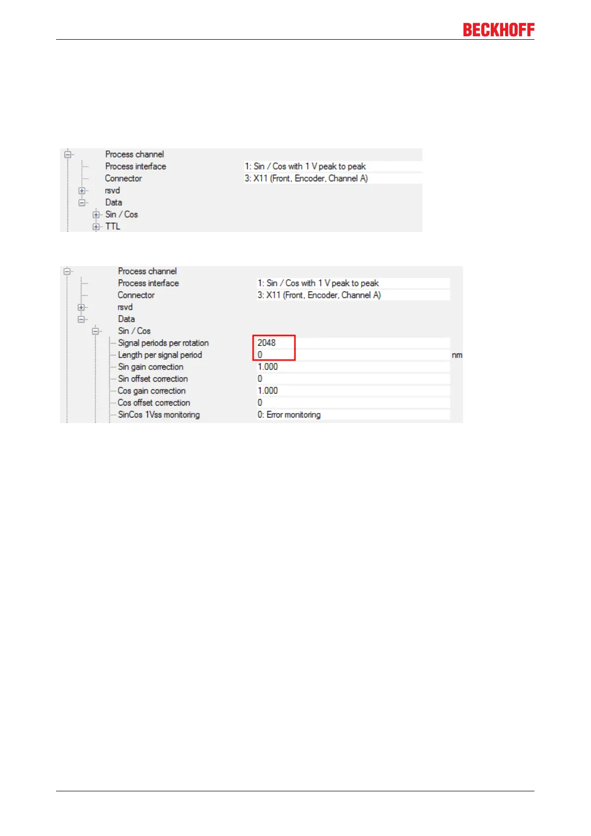
"Process interface" is "1: Sin / Cos with 1 V peak to peak" in case the encoder provides those signals. In
case of pure digital communication it is " 5: Digital interface".
Doublecheck the connector setting.
In case of a rotary encoder with digital interface only you are done with the process channel.
In case of an encoder with sin / cos signals or a linear encoder please proceed to "Data/ Sin / Cos":
For a rotary encoder with sin/ cos signals please set the correct number of "Signal periods per rotation".
For a linear encoder please set the "Length per signal period" in nm. This is required also in case there are
no sin/ cos signals. Together with the "Signal periods per rotation" this value defines one rotation. If you run
a linear motor with a linear encoder you should set these values to get
Pole pitch = Length per signal period x Signal periods per rotation
Example:
Linear motor pole pitch = 24 mm
Length per signal period = 20000 nm (20 µm)
• → Signal periods per rotation = 24 mm / 20000 nm = 1200

 Loading...


