Power Management
Function description 71
Version: 1.5
16.2 DC supply
For special applications it may be useful to input a DC voltage. Several things need to be observed for the
connection and the parameter settings, which are described below.
The DC voltage can be connected:
• via the AC input (X01) or
• directly into the DC link (X02).
Voltage parameterization
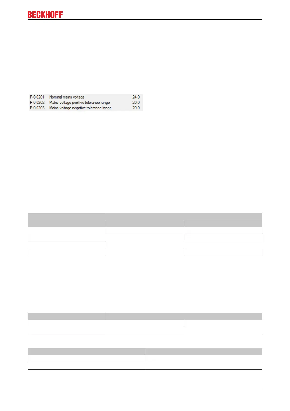
The desired DC voltage is set with P-0-0201
“Nominal mains voltage”. The controller automatically
recognizes the DC voltage form during the
initialization (from firmware v2.10).
In the case of small DC voltages, the parameters
P-0-0202 and P-0-0203 “Mains voltage tolerance”
should be 24 V or 48 V (at least 20%, better 30%).
Due to the tolerances when measuring the voltages,
an error would otherwise frequently be caused.
If the exchange of energy between several AX5000 devices is desired, the following parameterization must
be used:
DC-Link connection mode (P-0-0214):
"0x0003: AX5x01-AX5x25 [X02] Static external DC Link connection"
DC input via the wide-range voltage input – X01
In the case of input via X01, note that (as with the single-phase connection) only two of the six rectifier
diodes conduct the current. The same limitations apply as to the power or output current (see startup
manual). The voltage can be connected at L1 and L3/N.
Terminal point Connection
3-phase 1-phase
L1 Phase L1 Phase L1
L2 Phase L2 not used
L3 / N Phase L3 Neutral conductor
PE Protective conductor Protective conductor
DC input via the DC link input – X02
The charging circuit for the DC link is inactive. The user must ensure that the starting current does not
become too high when the voltage is switched on.
For the calculation, for example, of a resistor that limits the starting current, the DC link of the AX5000 is to
be regarded as a short-circuit at the moment of switching on.
Be sure to observe the correct polarity of the connection (DC+, DC-)!
Terminal point Connection
DC + DC link + External brake resistor and DC link
connection
DC - DC link -
The table below shows values that may not be exceeded:
Device Max. starting current
AX5x01 – AX5112 10A
AX5118 – AX5140 20A

 Loading...


