Internal velocity filters
Function description42
Version: 1.5
8.5.1 Parameterisation of the filter
WARNING
Warning, risk of injury from uncontrolled movements!
Impermissible damping values lead to a strong phase shift, which can result in uncontrolled
acceleration of the motor and other instable states.
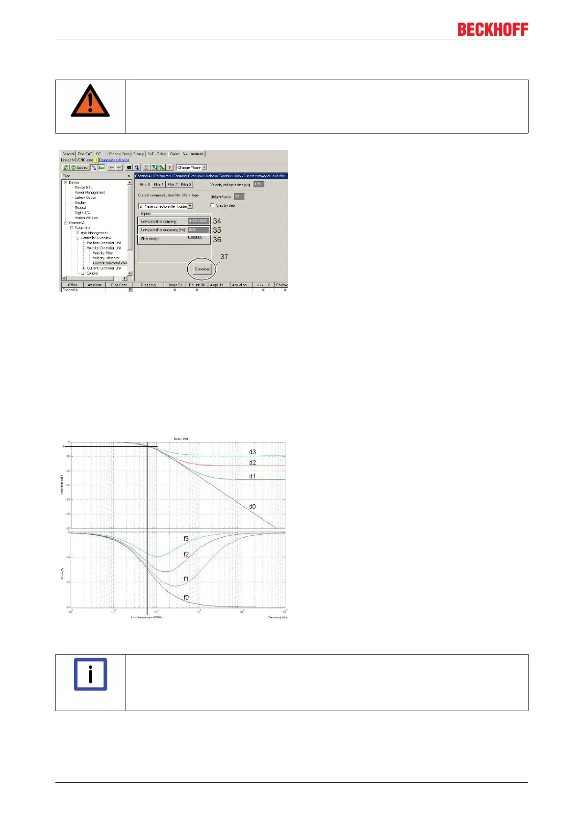
This filter is parameterised with the parameters "Limit
frequency" (35) and "Damping" (34). The time
constant (36) is calculated from the limit frequency
according to the following equation --> "Time
constant [s] = 1/ (2*Pi*Limit frequency [Hz])".
Determination of the limit frequency
The following test provides information about possibly
existing interference frequencies: Drive through the
necessary operating speed range and make a scope
recording of the actual active current (IDN S-0-0084).
A frequency analysis shows possibly existing
resonance points.
Click on the "Download" button (37) to conclude the
parameterisation. If you are online these parameters
are loaded directly into the AX5000 and activated. If
you are offline they are only written into the start-up
list.
The limitation of the damping of the amplitude
ensures that the phase shift returns to zero. The
limited damping is adequate for most drive
applications.
Example:
With this example the frequency response of the PT1
filters has been illustrated for clarity. The Bode plot
(logarithmic frequency curve) shows the amplitude
over frequency in the upper area and the associated
phase shift over frequency in the lower area. Seen
together, it is recognisable that a phase shift results
from the damping of the amplitude.
Parameter inputs in the TCDriveManager:
Time constant = 0.000025 s
(Limit frequency = 6280 Hz)
Damping:
d0 = 0
d1 = 0.05
d3 = 0.15
d4 = 0.35
"Phase correction filter 1. order" – method – "step by step"
Note
Expert hint!
The software calculates the coefficients independently using the parameters entered. If you
have sufficient experience in control technology you can also determine the coefficients
yourself and thus affect the behaviour of the filter.
The method is the same as in the "Notch filter classic method" – "step by step".

 Loading...


