Internal velocity filters
Function description36
Version: 1.5
8 Internal velocity filters
WARNING
Warning, risk of injury from uncontrolled movements!
When working with the described filters there is always a danger of the motor performing
uncontrolled movements due to impermissible parameterization. Make sure that your appli-
cation allows these movements and secure the entire danger zone against inadvertent en-
try; ensure that no persons are in the danger zone.
Note
Application of the Velocity Observer!
Above a frequency of 300 Hz noise can become problematic. First and second-order filters
are often ineffective in this case. The Velocity Observer of the AX5000 servo drive provides
the velocity controller with a speed signal available without resonance-induced oscillations
over the widest possible frequency range. It is available in FW v2.06 in Basic mode (third
order) and in FW v2.10 in Advanced mode (fifth order).
Further information can be found in chapter: „Velocity Observer“ of this function manual.
The control quality describes the capacity of the drive system to follow the setpoint values highly
dynamically, with low losses and fail-safe. The control quality depends on many factors. On the mechanical
side these could be soft drive trains with belt drive, or resonance points caused by the natural ageing of
components or special features of the mechanical structure. Without the use of filters the only possibility is to
reduce the loop gain and to adapt it to the worst condition. However, this adaptation affects the total
application and lowers the dynamics of the drive system. The application and the parameterization of the
internal speed and current filters act, for example, specifically on a resonant frequency, hence allowing a
high loop gain and thus a highly dynamic drive system. The filters described here serve to eliminate or
attenuate unwanted noise or resonant frequencies. The main control loops of a servo drive are the position
controller, the velocity controller and the current controller. With the exception of the position controller,
software filters can be inserted before the controllers. The characteristic of these special software filters is
realized by means of a 1st and 2nd order IIR filter with time-discrete transfer function.
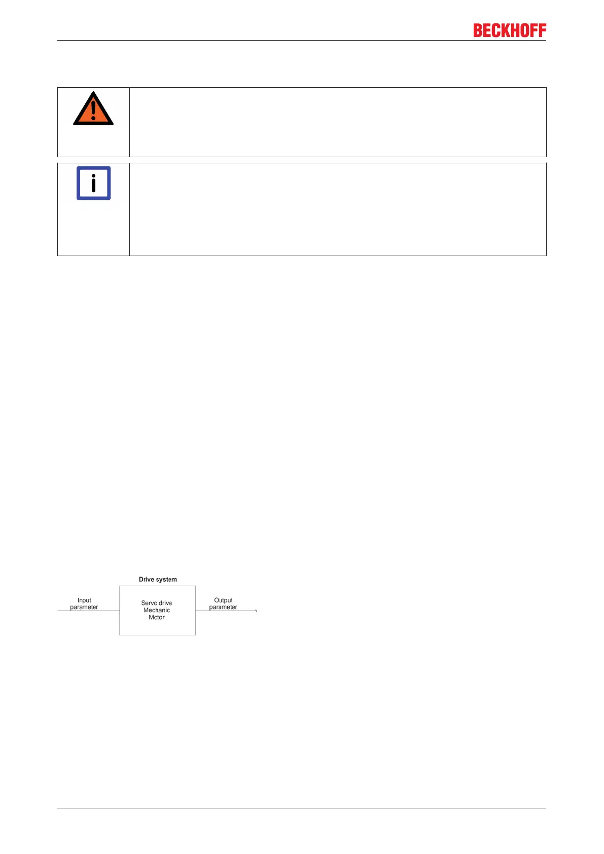
8.1 Basic principles
The drive system receives the input parameter "Speed n = 40 rpm" from the PLC. If the drive system is
operating under optimum conditions, the motor achieves this speed with very good control quality. The
different characteristics of the drive system also cause sources of resonance among other things, which are
always disturbing. They often manifest themselves in oscillating shafts or hum frequencies. Overlaid signal
oscillations of the encoder systems can similarly create high frequency noise, thus reducing the control
quality.
The following test provides information about possibly existing interference frequencies: Drive through the
necessary operating speed range and make a scope recording of the actual active current (IDN S-0-0084).
On the basis of the curve of the graph you can judge whether or not there are points of interference.

 Loading...


