Internal velocity filters
Function description 41
Version: 1.5
Example:
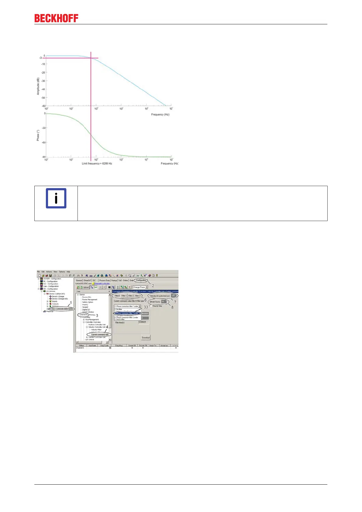
With this example the frequency response of the PT1
filters has been illustrated for clarity. The Bode plot
(logarithmic frequency curve) shows the amplitude
over frequency in the upper area and the associated
phase shift over frequency in the lower area. Seen
together, it is recognisable that a phase shift results
from the damping of the amplitude.
Parameter inputs in the TCDriveManager:
Limit frequency = 6280 Hz
(Time constant = 0.025343)
"1
st
order low pass filter" – method – "step by step"
Note
Expert hint!
The software calculates the coefficients independently using the parameters entered. If you
have sufficient experience in control technology you can also determine the coefficients
yourself and thus affect the behaviour of the filter.
The method is the same as in the "Notch filter classic method" – "step by step".
8.5 1st order phase correction filter
The 1
st
order phase correction filter attenuates all
frequencies above the limit frequency entered. Select
a servo drive (1) in the TwinCAT System Manager,
start the TCDriveManager (2), click on the respective
axis (3) and select the "Current command value
filter" (4).
A maximum of four filters are evaluated, which can be
parameterised independently of one another. In area
(6), activate the filter that you would like to occupy
with the phase correction filter. The cycle time of the
velocity controller is indicated in field (7). The "QMath
Factor" (8) determines the scaling of the filter input
parameter. With the current filter implementation the
maximum possible resolution is achieved with the
default value "30".
Now select "Phase correction filter 1. order" (33) from
the drop down menu.

 Loading...


