Power Management
Function description72
Version: 1.5
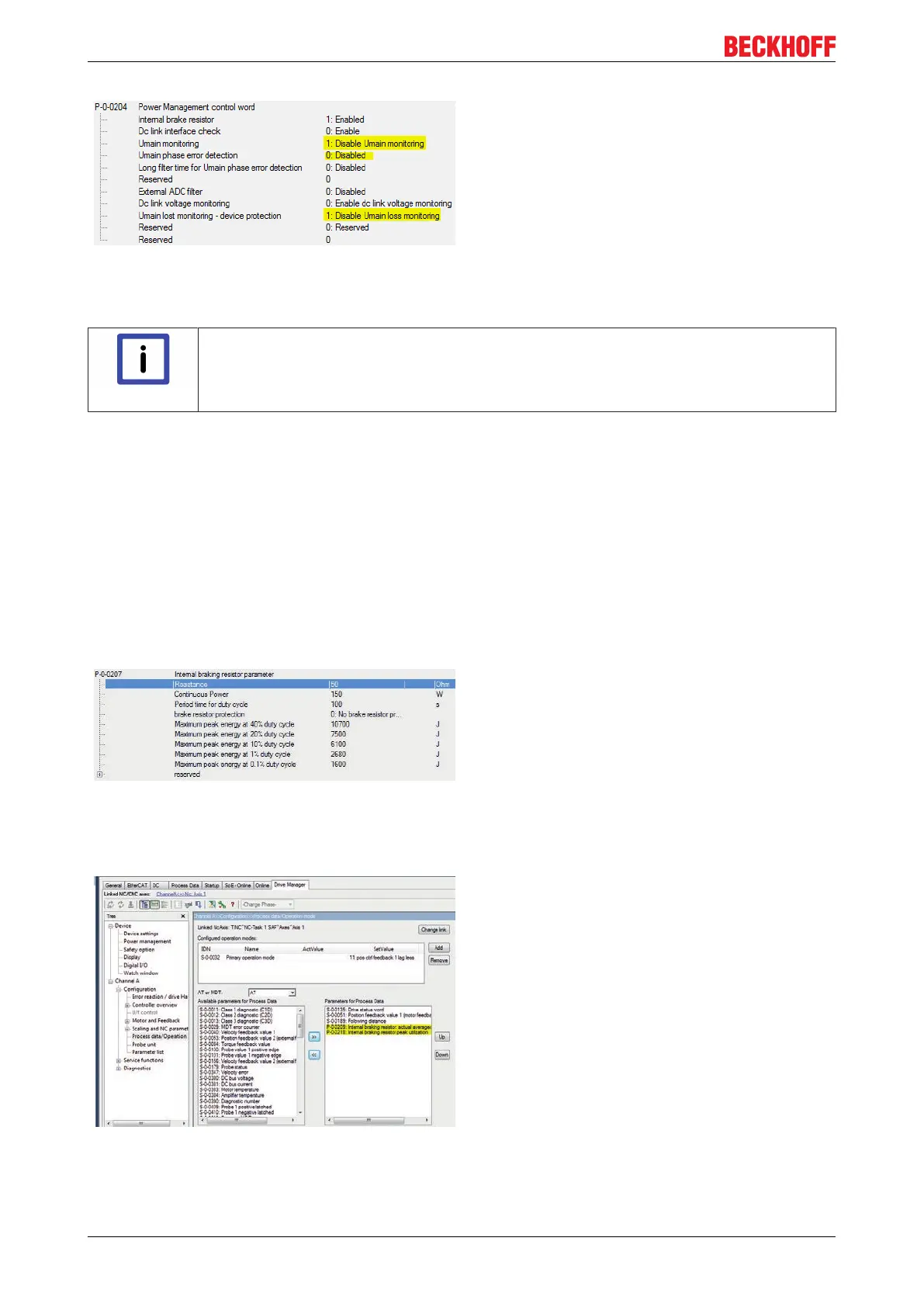
The settings in the Power Management Control Word
(P-0-0204) marked below are important in the case of
input via X02 (from firmware V2.10):
Important! With the parameterization “Disable Umain
loss monitoring”, the device protection with regard to
mains voltage interruptions at X01 is switched off.
Therefore, only switch the monitors off in case of DC
input at X02.
16.3 Diagnostics for external brake resistors
Note
Reference values for the external brake resistor:
P-0-0207; P-0-0208; P-0-0209; P-0-0210; P-0-0218; P-0-0219; P-0-0220; P-0-0221
This chapter provides basic information on dimensioning and configuration of external brake resistors. The
parameters described in this chapter can be recorded with the TwinCAT Scope View for diagnostic
purposes.
If an internal brake resistor is used, the configuration takes place via the IDNs:
• P-0-0209 (Internal brake resistor actual continuous power) in watts and
• P-0-0218 (Internal brake resistor actual peak energy) in %
If an external brake resistor is used, the configuration takes place via the IDNs:
• P-0-0210 (External brake resistor actual continuous power) in watts and
• P-0-0219 (External brake resistor actual peak energy) in %
"Actual continuous power" is an arithmetically
averaged value of the actual power. Even after
several typical machine cycles the value of P-0-0210
(P-0-0209 internally) must always remain below the
value of the continuous power of the brake resistor.
A cycle time of 100 s is assumed for calculating the
brake resistor power. Monitoring should therefore
take place over this time as a minimum. The
permissible value for the continuous power can be
found in P-0-0207 (internal brake resistor) or
P-0-0208 (external brake resistor):
"Actual peak energy" indicates the greatest measured
braking energy, much like a drag indicator does. The
situation with the maximum required peak braking
power, e.g. emergency stop, is supposed to be
determined and tested. In the process, the value of
P-0-0218 (internal) or P-0-0219 (external) should stay
considerably below 100%.
For more exact observations it is possible to record
the parameters with the software oscilloscope. If for
example the velocity or the position is recorded, a
better allocation of the current braking power to the
machine cycle is possible. To this end the parameters
must be inserted into the process image beforehand:

 Loading...


