Internal velocity filters
Function description 39
Version: 1.5
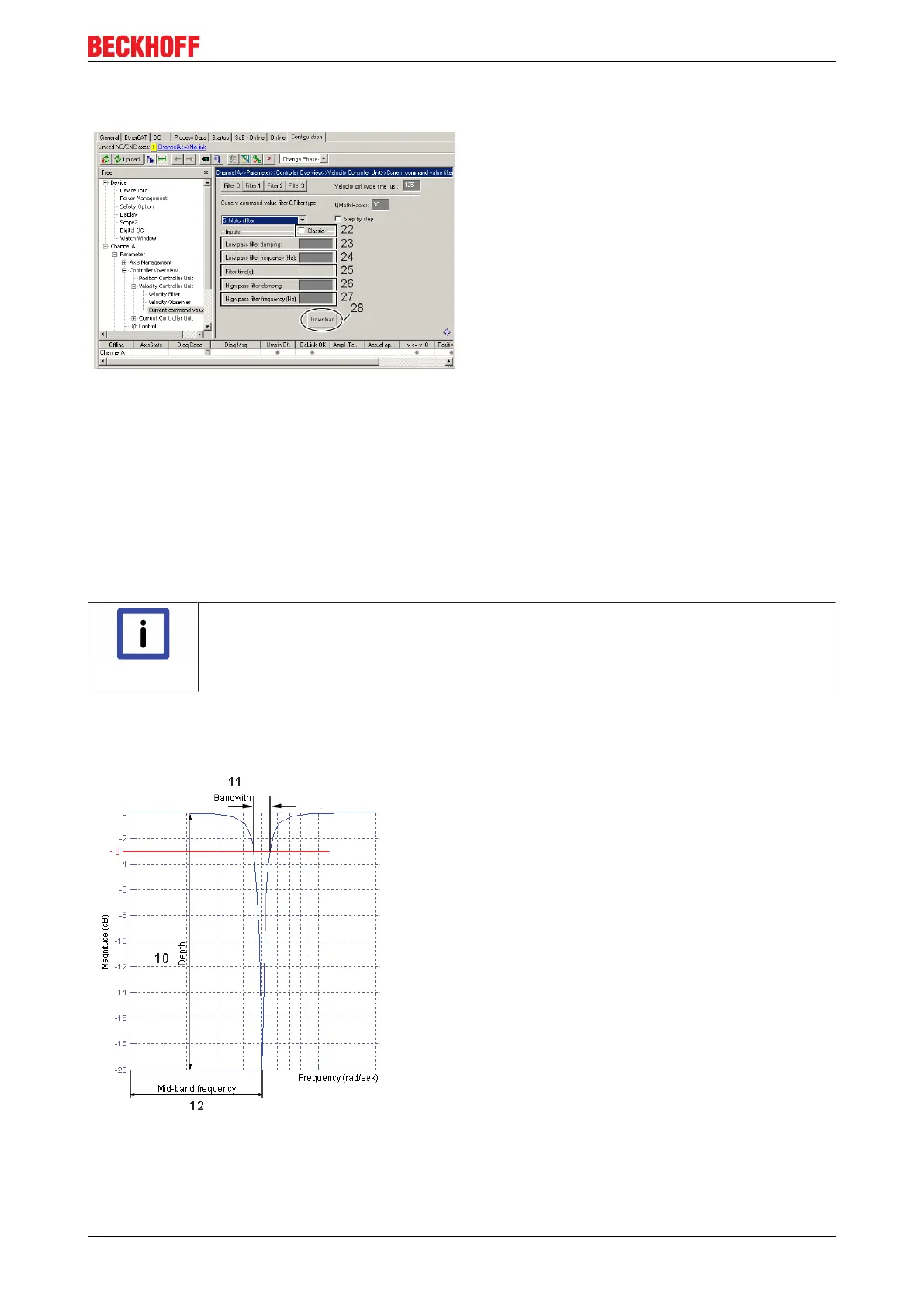
"Low-pass and high-pass filter" method
This variant is activated by unchecking the "Classic"
checkbox (22).
You must now determine and enter the parameters
"Low pass filter damping" (23), "Low pass filter
frequency" (24), "High pass filter damping" (26) and
"High pass filter frequency" (27); the "Filter time" (25)
is calculated by the software in relation to the "Low
pass filter frequency" (24). If you wish to emulate the
classic method, you must enter the centre frequency
plus half the bandwidth in field (24) and the centre
frequency minus half the bandwidth in field (27). The
depth (10) is determined with the damping (23) or
(26); see the diagram "Bode Plot" below for this. The
parameters entered lead internally to the calculation
of the coefficients b
0
, b
1
, b
2
, and a
1
, a
2
(see the above
diagram "1
st
and 2
nd
order IIR filter" for this).
Using the methods described you can also map any
unbalances of the notch filter, among other things.
Click on the "Download" button (28) to conclude the
parameterisation. If you are online these parameters
are loaded directly into the AX5000 and activated. If
you are offline they are only written into the start-up
list.
"Low-pass and high-pass filter" method – step by step
Note
Expert hint!
The software calculates the coefficients independently using the parameters entered. If you
have sufficient experience in control technology you can also determine the coefficients
yourself and thus affect the behaviour of the filter.
The method is the same as in the "Classic method" – step by step.
Bode Plot

 Loading...


