EasyManua.ls Logo

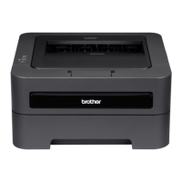
Brother HL-2230 User Manual

Brother HL-2230
181 pages
To Next Page IconTo Next Page
To Previous Page IconTo Previous Page
Page #146 background imageLoading...
Page #146 background image
5-1
Confidential
CHAPTER 5 SERVICE FUNCTIONS
The maintenance mode is exclusively designed for the purpose of checks, settings and
adjustments using the buttons on the control panel or open/close of the front cover. You can
perform operational checks of sensors, perform a print test, display the log information or
error codes.
Various modes can be used if the power switch is set to ON while the [Go] button is held.
There are two types of modes: End user-accessible maintenance mode and Service
personnel-accessible maintenance mode. Three types of LED display are used to indicate
that present state.
LED indication Contents
Toner/Drum/Error LEDs
light up at the same
time
Show that transfer to the specified mode is completed.
Ready LED lights up Show that the [Go] button is held when the mode or function
is selected. Ready LED lights off if the [Go] button is not
held.
All LEDs light for 1
second at the same
time
Show that initialization or change of set values is completed.
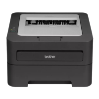
Table of Contents

Questions and Answers:

Brother HL-2230 Specifications

General IconGeneral
Network readyNo
Print technologyLaser
Maximum resolution2400 x 600 DPI
Time to first page (black, normal)8.5 s
Print speed (black, normal quality, A4/US Letter)24 ppm
Printing colorsBlack
Maximum duty cycle- pages per month
Number of print cartridges1
Sound power level (standby)31 dB
Sound pressure level (printing)53 dB
Total input capacity250 sheets
Total output capacity- sheets
Custom media width76.2 - 220 mm
Maximum print size216 x 356 mm
Custom media length116 - 406.4 mm
Paper tray media typesBond paper, Plain paper, Pre-Printed
Paper tray media weight60 - 105 g/m²
Non-ISO print media sizesExecutive (184 x 267mm), Folio (media size), Letter (media size), Legal (media size)
ISO A-series sizes (A0...A9)A4, A5, A6
ISO B-series sizes (B0...B9)B5, B6
Maximum ISO A-series paper sizeA4
Standard interfacesUSB 2.0
Windows operating systems supportedYes
AC input voltage120 V
AC input frequency50 - 60 Hz
Power consumption (off)0.9 W
Power consumption (printing)495 W
Power consumption (PowerSave)65 W
Package weight8000 g
Compatible operating systemsWindows 2000 Professional, XP Home Edition, XP Professional Edition, XP Professional x64 Edition, Server 2003, Server 2003 x64 Edition, Vista, Server 2008, Server 2008 R2, Windows 7 Mac OS X 10.4.11, 10.5.x, 10.6.x
Sustainability certificatesENERGY STAR
Storage temperature (T-T)10 - 32.5 °C
Operating relative humidity (H-H)20 - 80 %
Bundled softwareInteractive Help
Weight and Dimensions IconWeight and Dimensions
Dimensions (WxDxH)368 x 360 x 183 mm

Summary

CHAPTER 1 SPECIFICATIONS

1.1 General

Provides general specifications like print method, resolution, speed, warm-up time, CPU, memory, etc.

1.2 Network Connectivity

Details wired and wireless network capabilities for different models.

1.3 Service Information

Information on printer life, MTBF, MTTR, and parts life.

1.4 Supplies

Details toner cartridge and drum unit specifications and yield.

1.5 Paper

Covers paper handling and media specifications for various paper types.

1.6 Printable Area

Shows the non-printable margins for different paper sizes.

CHAPTER 2 TROUBLESHOOTING

1. INTRODUCTION

Introduces troubleshooting procedures and essential precautions for service personnel.

2. OVERVIEW

Provides cross-section drawings, paper feeding paths, and component descriptions.

3. LED ERROR INDICATION AND FAILURES

Explains LED error codes at operator and service calls for fault diagnosis.

4. ERROR SYMPTOM/ERROR CAUSE AND REMEDY

Lists common error symptoms with causes and remedies for troubleshooting.

CHAPTER 3 DISASSEMBLY AND ASSEMBLY

1. SAFETY PRECAUTIONS

Essential safety measures to follow before and during maintenance.

2. PACKING

Illustrates the packing procedure and components for shipping or storage.

3. SCREW CATALOGUE

Lists and illustrates various screw types used in the printer assembly.

4. SCREW TORQUE LIST

Specifies the correct tightening torque for different screws during assembly.

5. LUBRICATION

Details lubrication points and quantities for specific parts.

6. OVERVIEW OF GEARS

Shows diagrams and names of gears in the paper feeder and development parts.

7. HARNESS ROUTING

Illustrates the routing paths for various wire harnesses within the printer.

8. DISASSEMBLY FLOW

Provides a flowchart showing the sequence of disassembly steps.

9. DISASSEMBLY PROCEDURE

Step-by-step instructions for disassembling various printer components.

CHAPTER 4 ADJUSTMENTS AND UPDATING OF SETTINGS, REQUIRED AFTER PARTS REPLACEMENT

1. IF YOU REPLACE THE MAIN PCB ASSY

Procedures for rewriting firmware, setting paper size, and serial number after PCB replacement.

2. IF YOU REPLACE THE LASER UNIT

Instructions for inputting adjusted values after replacing the laser unit.

3. IF YOU REPLACE THE LOW VOLTAGE POWER SUPPLY PCB ASSY

Procedure for resetting the irregular power supply detection counter.

CHAPTER 5 SERVICE FUNCTIONS

1. MAINTENANCE MODE

Explains how to enter and use end-user and service maintenance modes.

2. PRINTER SETTINGS

Details how to print printer configuration and maintenance information.

3. OTHER SERVICE FUNCTIONS

Covers functions like reprint, job cancel, wireless settings, and drum cleaning.

CHAPTER 6 CIRCUIT DIAGRAMS, WIRING DIAGRAM

CHAPTER 7 PERIODICAL MAINTENANCE

1. PERIODICAL REPLACEMENT PARTS

States that there are no parts requiring periodic replacement.

REGULATION

<For USA and Canada>

Federal Communications Commission (FCC) Declaration of Conformity (For USA)

FCC compliance statement for USA regarding radio frequency emissions.

Industry Canada Compliance Statement (For Canada)

Laser Safety (110 to 120 volt model only)

FDA Regulations (110 to 120 volt model only)

SAFETY INFORMATION

Caution for Laser Product (WARNHINWEIS fur Laser drucker)

Warnings and cautions related to laser product safety during servicing.

Additional Information

Important notes on handling the optical system and laser beam safety.

Definitions of Warnings, Cautions, Notes and Memos

Safety Precautions

APPENDIX 1 SERIAL NUMBERING SYSTEM

Serial number labels for the printer itself

Explains how to read and interpret the printer's serial number label.

APPENDIX 2 DELETION OF USER SETTING INFORMATION

APPENDIX 3 INSTALLING THE MAINTENANCE PRINTER DRIVER

APPENDIX 4 HOW TO MAKE PROTECTIVE MATERIAL OF DRUM UNIT

In the case of old type Paper strip

Instructions for creating protective material using old-style paper strips.

In the case of new type Paper strip

Instructions for creating protective material using new-style paper strips.

Related product manuals