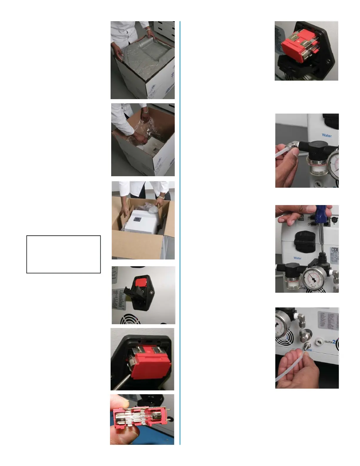
1. Carefully open the shipping
carton. Lift the foam protec-
tor from the carton, expos-
ing the plastic-covered
Sprint instrument.
2. Lift the protective plastic,
exposing the instrument.
3. Using the provided lifters,
carefully lift the instrument
from the carton and place it
on a sturdy work bench with
the back of the instrument
positioned so that all con-
nections can be accessed.
CAUTION
Do not attempt to lift
the instrument by the
top cover.
4. Using a small fl at blade
screwdriver, open the cover
of the power entry module,
exposing the fuse holder.
5. Using a small fl at blade
screwdriver, remove the
fuse holder from the power
entry module.
6. Based on electrical require-
ments, install the two (2)
applicable fuses in the fuse
holder.
10 AMP for 120V (BR188270)
5 AMP for 240V (BR188280)
System Setup
2
7. Install the fuse holder into
the power entry module and
close the cover.
8. Unscrew the cap from the
connector of the water/fi lter
regulator. Note: Retain the
cap for reuse if the instru-
ment requires relocation
or return to CEM for repair.
Refer to the “Maintenance,
Troubleshooting and Ser-
vice” section of this manual.
9. Locate the 10’ length of tub-
ing shipped with the instru-
ment. Connect one end of
the tubing to the connector
on the water fi lter/regula-
tor assembly, and the other
end to a laboratory water
source.
10. Turn on the water source to
supply water to the instru-
ment.
11. The pressure gauge on
the fi lter/regulator assem-
bly is factory set to 10 psi.
If necessary to reset the
pressure, rotate the pres-
sure adjusting nut clockwise
(right facing back of instru-
ment until the gauge on the
fi lter/regulator assembly
indicates 10-15 psi. Note:
If any water leakage is de-
tected, discontinue system
installation and contact
CEM Service.
12. Remove the black cap
from the connector labeled
“Waste.” Note: Retain the
cap for reuse if the instru-
ment requires relocation
or return to CEM for repair.
Refer to the “Maintenance,
Troubleshooting, and Ser-
vice” section of this manual.
13. Using the length of 1/4”
silicon waste tubing, con-
nect one end of the tubing
to the waste connector on
the back of the instrument.
Position the other end of
the waste tubing in a waste
bottle, sink or other suitable
waste container.
 Loading...