Cabling the Switch Processor Input/Output Line Card
▀ Connecting to a BITS Timing Source
▄ ASR 5000 Installation Guide
BITS T1 3-Pin Interface
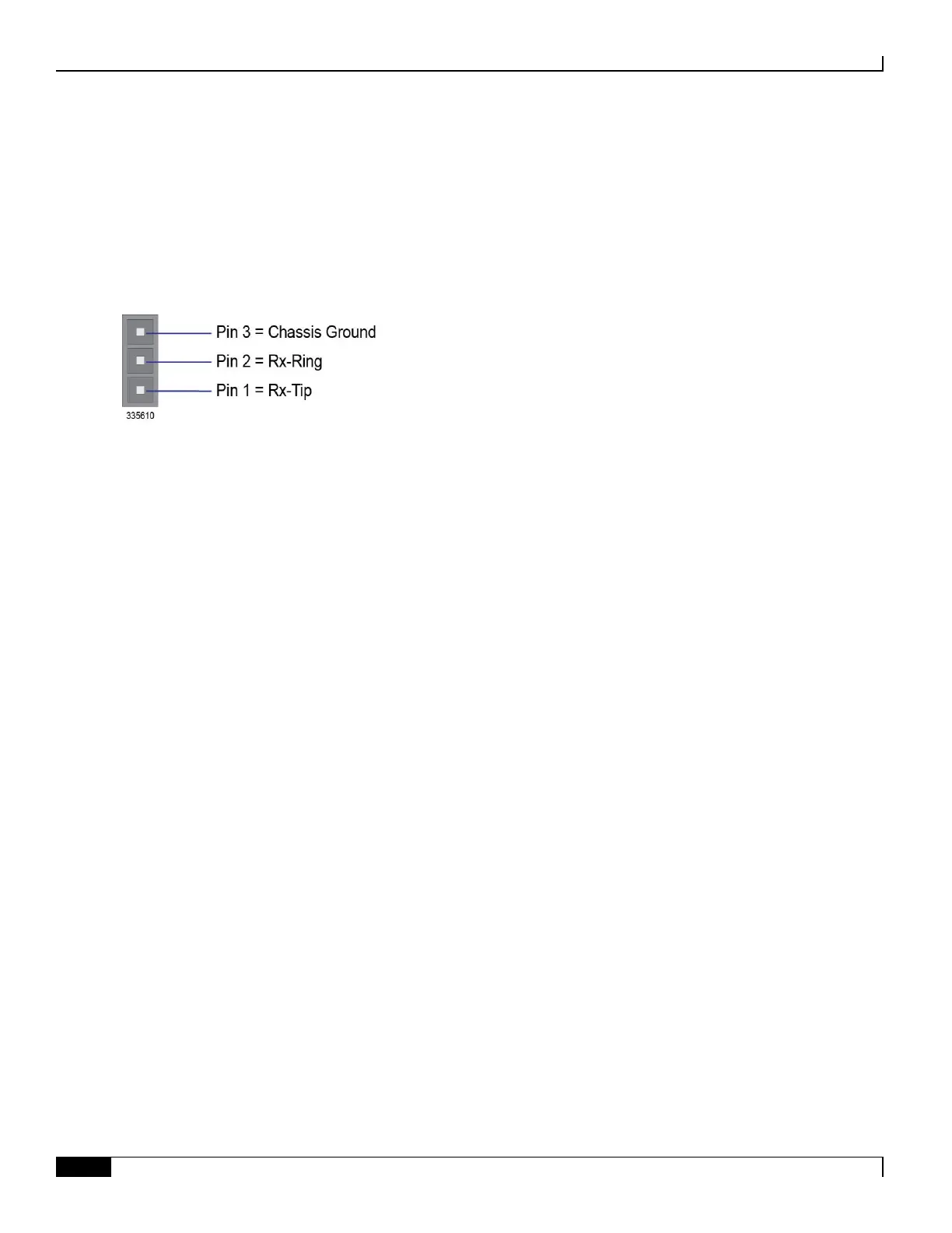
The 3-pin version of the SPIO employs a wire-wrap connector that accepts a T1 (DS1) BITS data signal (all ones). The
following figure shows the BITS timing interface wire-wrap pin-out.
Figure 37. SPIO T1 BITS Wire-Wrap Pinout
Use 22 AWG, twisted-pair, 100-ohm shielded cable between the BITS and SPIO wire-wrap interface to carry the DS1
signal.
BITS Timing Configuration
After connecting the BITS interface to the BITS, you must use the CLI to configure the type of timing signal being
supplied to the SPIO. Options include:
E1 Frame Alignment Signal (FAS)
E1 Multiframe with CRF (FAS+CRC)
T1 Extended Superframe Format (ESF)
T1 Superframe Format (D4)
For additional information on BITS configuration, refer to the BITS Port Configuration Mode Commands chapter of the
Command Line Interface Reference.

 Loading...


