Applying Power and Verifying the Installation
Verifying the Installation ▀
ASR 5000 Installation Guide ▄
Table 75. Channelized Line Card Standby LED States
Card is in redundant mode
None needed for line cards installed in slots 33 through 39 and 42 through 48 after
configuration.
If green for line cards installed in slots 17 through 23 and 26 through 32, refer to the
System Administration Guide for troubleshooting information.
Card in Ready Mode
OR
Card is not receiving power
OR
Card in Active Mode
This is normal prior to configuration. Neither the Active nor Standby LEDs on the card
will be on.
Verify that the Run/Fail LED is green. If so, the card is receiving power and POST test
results are positive. If it is off, refer to Channelized Line Card Run-Fail LED States for
troubleshooting information.
Check the state of the Active LED. If it is green, the card is in standby mode.
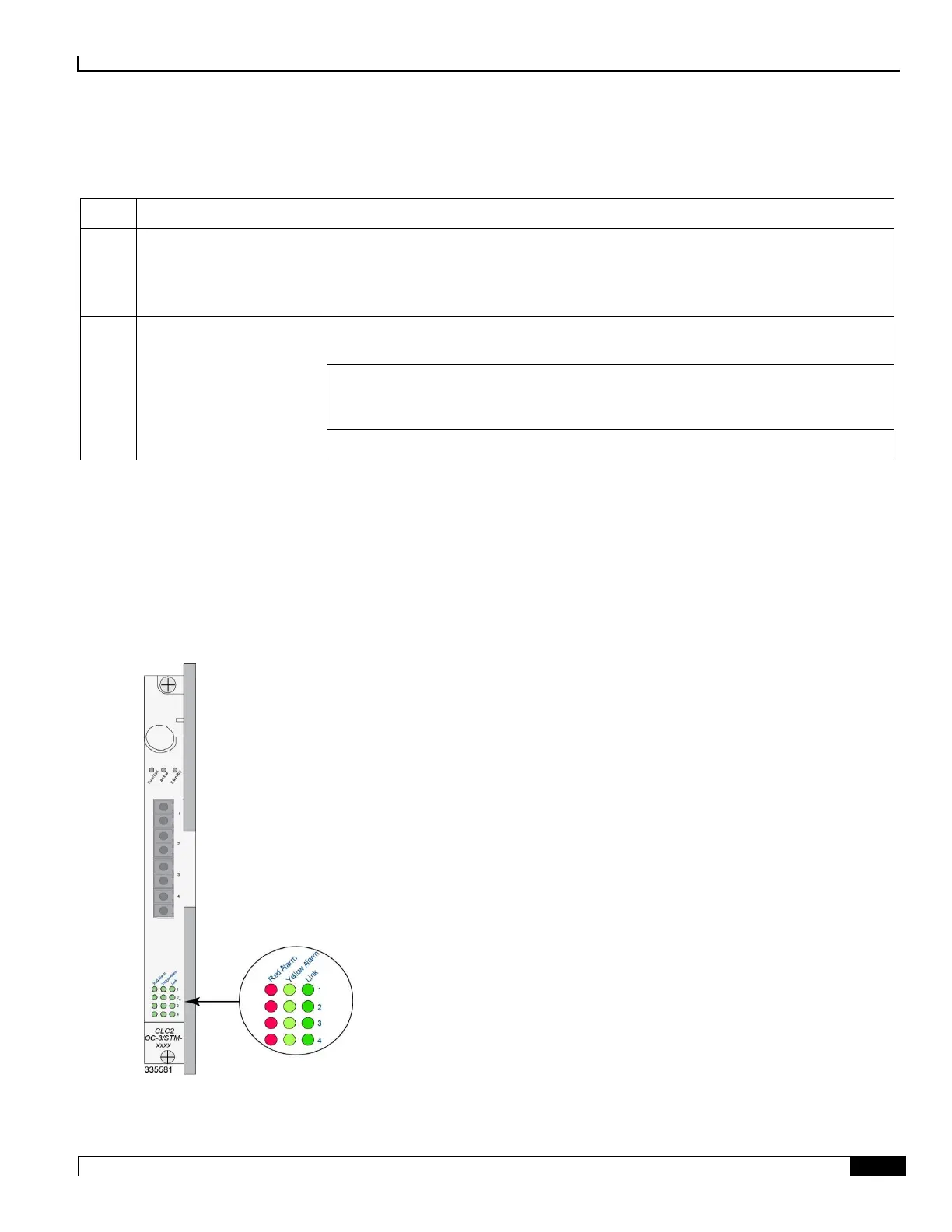
Checking the Alarm and Link LEDs on the Channelized Line Card 2
Each CLC2 provides alarm and link LEDs that indicate the status of each port. These LEDs are located at the bottom of
the front panel, as illustrated in the figure below.
Figure 58. Alarm/Link LEDs for the Channelized Line Card

 Loading...


