ASR 5000 Hardware Platform Overview
▄ ASR 5000 Installation Guide
Power Filter Units
Located at the bottom rear of the chassis are slots for two 165-amp Power Filter Unit (PFU) assemblies. Each PFU
provides DC power from the site’s power distribution frame (PDF) to the chassis and its associated cards. Each load-
sharing PFU operates independently of the other to ensure maximum power feed redundancy. The maximum input
operating voltage range of the PFU is -40 VDC to -60 VDC; the nominal range is -48 VDC to -60 VDC.
Important: The ASR 5000 does not offer an AC power supply option. If only AC power is available at the
installation site, an adequately sized AC-to-DC converter will be required to supply -48 VDC power to the chassis.
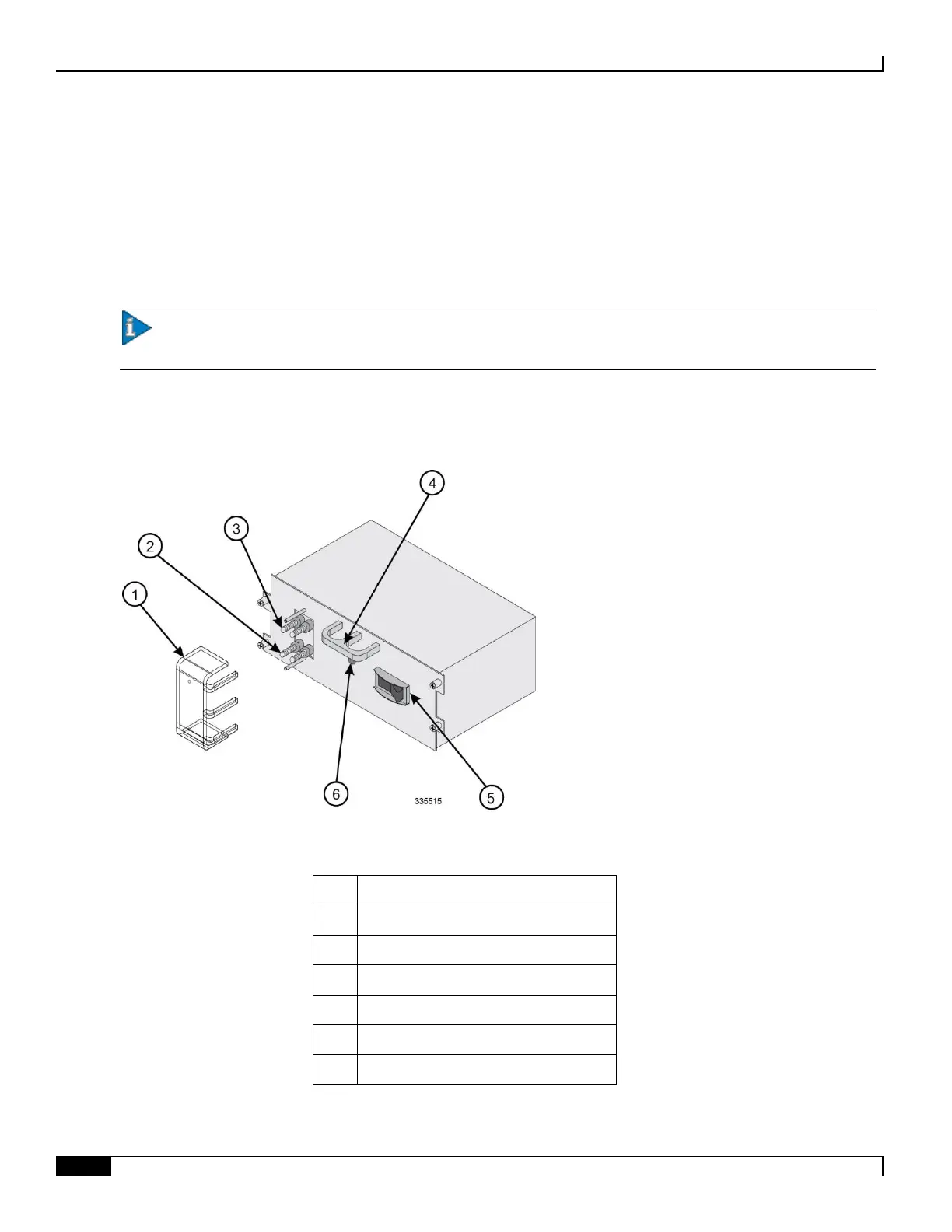
The following drawing shows the PFU and its connectors.
Figure 6. PFU Components
Table 5. Power Filter Unit Component Descriptions
VDC (-48 VDC input terminals)
RTN (voltage return terminals)
Circuit breaker (On/Off) rated at 165A

 Loading...


