ASR 5000 Hardware Platform Overview
ASR 5000 Installation Guide ▄
Line Cards
The following rear-loaded cards are currently supported by the system.
Switch Processor I/O (SPIO) Card
The SPIO card provides connectivity for local and remote management, CO alarming, and Building Integrated Timing
Supply (BITS) timing input. SPIOs are installed in chassis slots 24 and 25, behind SMCs. During normal operation, the
SPIO in slot 24 works with the active SMC in slot 8. The SPIO in slot 25 serves as a redundant component. In the event
that the SMC in slot 8 fails, the redundant SMC in slot 9 becomes active and works with the SPIO in slot 24. If the SPIO
in slot 24 should fail, the redundant SPIO in slot 25 takes over.
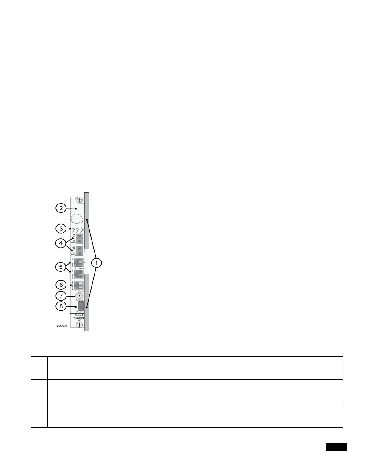
The following shows the front panel of the SPIO card, its interfaces, and other major components.
Figure 12. Switch Processor I/O (SPIO) Card
Table 8. SPIO Callouts
Card Ejector Levers—Use to insert/remove card to or from the chassis.
Interlock Switch—In its Down position the interlock switch notifies the system to safely power down the card prior to
its removal.
Card Level Status LEDs—Show the status of the card.
Optical Gigabit Ethernet Management LAN Interfaces—Two Small Form-factor Pluggable (SFP) optical Gigabit
Ethernet interfaces to connect optical transceivers.

 Loading...


