Cabling the Switch Processor Input/Output Line Card
Connecting to the CO Alarm Interface ▀
ASR 5000 Installation Guide ▄
Connecting to the CO Alarm Interface
The Central Office (CO) Alarm interface utilizes a 10-pin Molex female-connector fro interconnection with the three
normally closed dry-contact relays. These relays trigger external audio and/or visual indicators for the following three
alarm levels:
Minor Alarm: This alarm is triggered when a high temperature is detected on a card, causing the fan tray to
switch its fans to high speed.
Major Alarm: This alarm is triggered by a:
Hardware failure that places a card in an off-line state
Power filter unit failure or removal from the chassis
Failure of one or more fans on either the upper or lower fan tray
Fan tray failure or either fan tray assembly is removed from the chassis
Critical Alarm: This alarm is triggered when a severe degradation in service is detected. For example, if the
system is supporting a large number of subscribers and packet processing cards are removed thus significantly
reducing the amount of available CPU and memory resources.
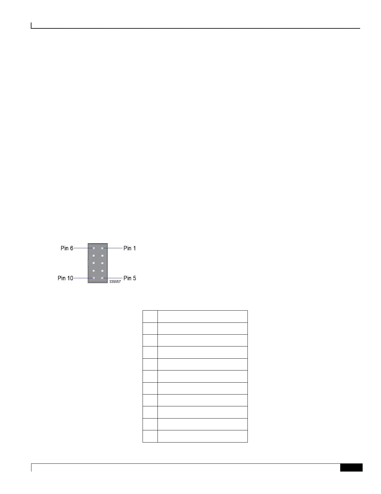
The CO alarm interface pinout is provided in the following figure and table.
Figure 38. SPIO CO Alarm Interface Pinouts
Table 37. SPIO CO Alarm Interface Pinouts
Major Alarm - Normally closed
Major Alarm - Normally open
Minor Alarm - Normally closed
Minor Alarm - Normally open
Critical Alarm - Normally closed
Critical Alarm - Normally open