ASR 5000 Hardware Platform Overview
▄ ASR 5000 Installation Guide
The XGLC is configured and monitored by the SMC via the system’s control bus. If the firmware needs to be upgraded.
the XGLC uses the Star Channel for a faster download.
Install XGLCs in chassis slots 17 through 23 and 26 through 32. These cards should always be installed directly behind
their respective packet processing cards, but they are not required behind any redundant packet processing cards (those
operating in Standby mode).
The supported redundancy schemes for XGLC are L3, Equal Cost Multi Path (ECMP) and 1:1 side-by-side redundancy.
Side-by-side redundancy allows two XGLC cards installed in neighboring slots to act as a redundant pair. Side-by-side
pair slots are 17-18, 19-20, 21-22, 23-26, 27-28, 29-30, and 31-32.
Side-by-side redundancy only works with XGLC cards. When configured for non-XGLC cards, the cards are brought
offline. If the XGLCs are not configured for side-by-side redundancy, they run independently without redundancy.
When you first configure side-by-side redundancy, the higher-numbered slot’s configuration is erased and then
duplicated from the lower-numbered slot. The lower-numbered top slot retains all other configuration settings. While
side by side redundancy is configured, all other configuration commands work as if the side by side slots were top-
bottom slots. Configuration commands directed at the bottom slots either fail with errors or are disallowed.
When you unconfigure side-by-side redundancy, the configuration for the higher-numbered top and bottom slots are
initialized to the defaults. The configuration for the lower-numbered slot retains all other configuration settings. If you
install non-XGLC cards in the slots, you may bring them back online.
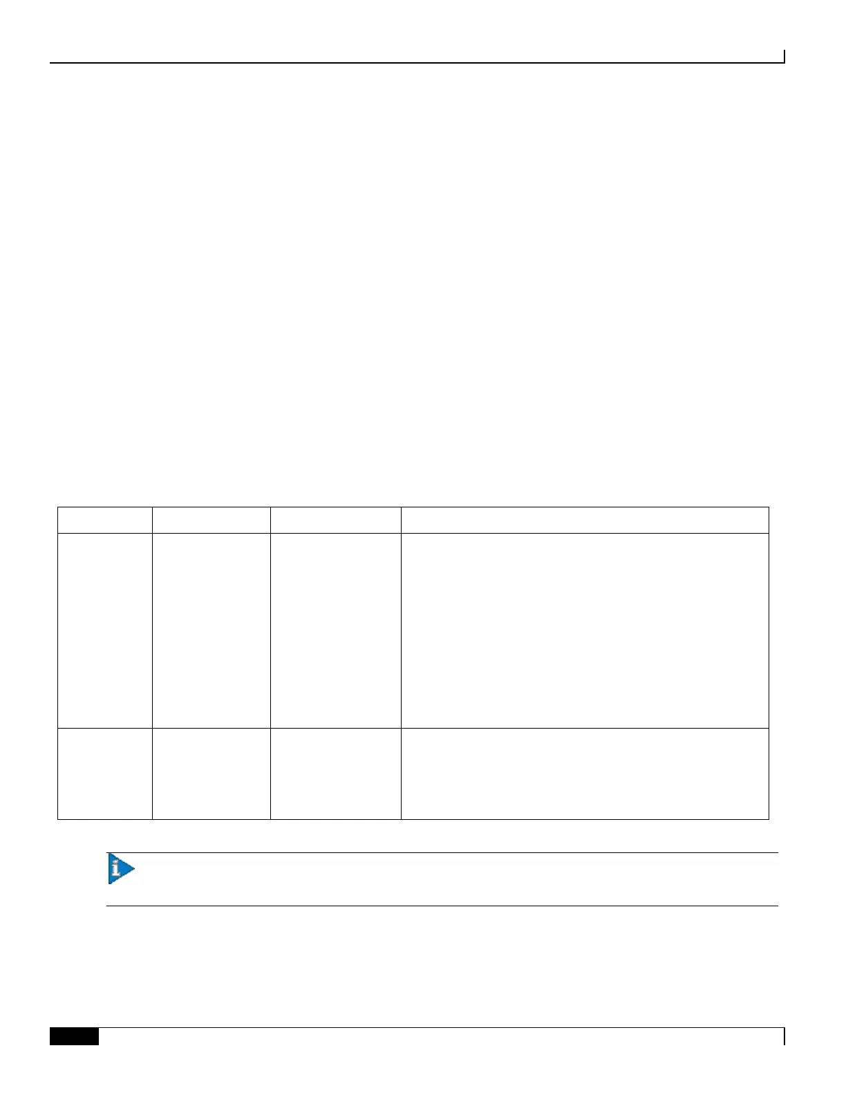
Table 16. SFP Modules Supported by the XGLC
Fiber, LC duplex
female connector
Fiber Type: Multi-mode fiber (MMF), 850 nm wavelength
Core Size (microns)/Range:
62.5/902.23 feet (275 meters)
50/1640.42 feet (500 meters)
62.5um/33m (OM1)
50um 500MHz-km/82m (OM2)
50um 2000MHz-km/300m (OM3)
Minimum Tx Power: -7.3 dBm
Rx Sensitivity: -11.1 dBm
Fiber, LC duplex
female connector
Fiber Type: Single-mode fiber (SMF), 1310 nm wavelength
Core Size (microns)/Range: 9/32808.4 feet (10 Kilometers)
Minimum Tx Power: -11.0 dBm
Rx Sensitivity: -19 dBm
Important: This product has been tested and found to comply with the limits for Class 1 laser devices for
IEC825, EN60825, and 21CFR1040 specifications.
The following shows the front panel of the XGLC, identifying its interfaces and major components:

 Loading...


