28-39
Catalyst 3550 Multilayer Switch Software Configuration Guide
78-11194-09
Chapter 28 Configuring Network Security with ACLs
Using VLAN Maps with Router ACLs
ACLs and Routed Packets
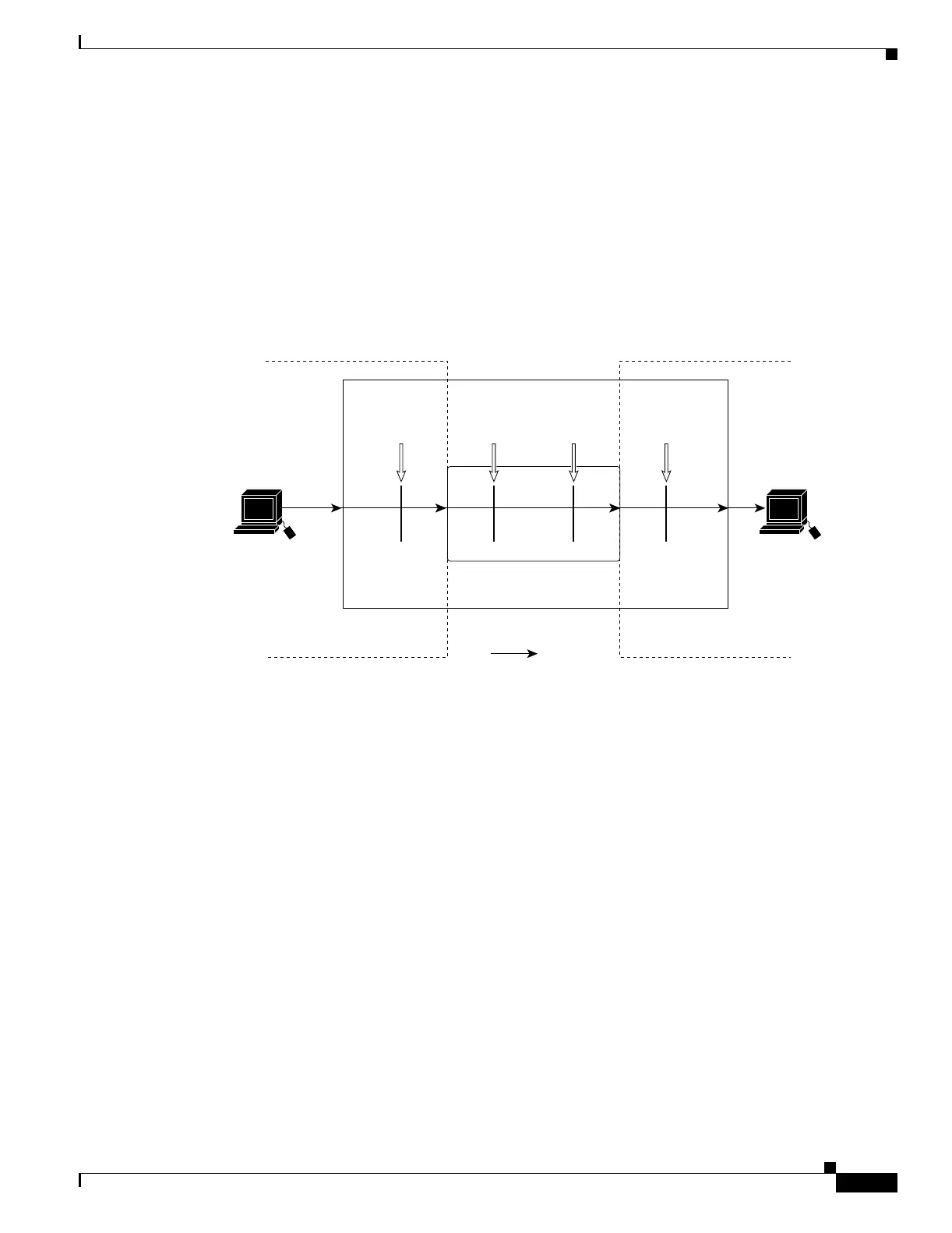
Figure 28-8 shows how ACLs are applied on routed packets. For routed packets, the ACLs are applied
in this order:
1. VLAN map for input VLAN
2. Input router ACL
3. Output router ACL
4. VLAN map for output VLAN
Figure 28-8 Applying ACLs on Routed Packets
Frame
Routing function
VLAN 10
Host A
(VLAN 10)
Packet
86308
Catalyst 3550 switch
VLAN 20
Host B
(VLAN 20)
VLAN 10
map
Input
router
ACL
Output
router
ACL
VLAN 20
map

 Loading...
