31-69
Catalyst 3550 Multilayer Switch Software Configuration Guide
78-11194-09
Chapter 31 Configuring IP Unicast Routing
Configuring Multi-VRF CE
• You cannot configure the Web Cache Communication Protocol (WCCP) and multi-VRF CE on the
same switch at the same time.
• When multi-VRF CE is configured, you cannot assign the same Hot Standby Routing Protocol
(HSRP) standby address to two different VPNs.
• VRF and policy-based routing (PBR) are mutually-exclusive on a switch interface. You cannot
enable VRF when PBR is enabled on an interface. In contrast, you cannot enable PBR when VRF is
enabled on an interface.
Configuring VRFs
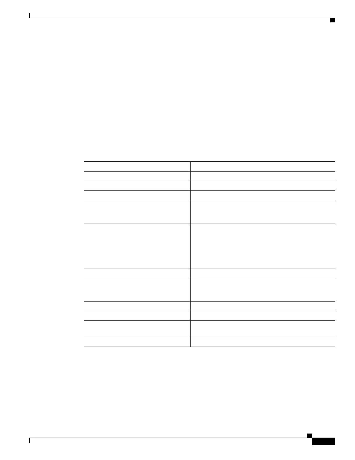
Beginning in privileged EXEC mode, follow these steps to configure one or more VRFs. For complete
syntax and usage information for the commands, refer to the switch command reference for this release
and the Cisco IOS Switching Services Command Reference for Release 12.1.
Use the no ip vrf vrf-name global configuration command to delete a VRF and to remove all interfaces
from it. Use the no ip vrf forwarding interface configuration command to remove an interface from the
VRF.
Command Purpose
Step 1
configure terminal Enter global configuration mode.
Step 2
ip routing Enable IP routing.
Step 3
ip vrf vrf-name Name the VRF, and enter VRF configuration mode.
Step 4
rd route-distinguisher Create a VRF table by specifying a route distinguisher.
Enter either an AS number and an arbitrary number
(xxx:y) or an IP address and abitrary number (A.B.C.D:y)
Step 5
route-target {export | import | both}
route-target-ext-community
Create a list of import, export, or import and export route
target communities for the specified VRF. Enter either an
AS system number and an arbitrary number (xxx:y) or an
IP address and an arbitrary number (A.B.C.D:y). The
route-target-ext-community should be the same as the
route-distinguisher entered in Step 4.
Step 6
import map route-map (Optional) Associate a route map with the VRF.
Step 7
interface interface-id Enter interface configuration mode and specify the Layer
3 interface to be associated with the VRF. The interface
can be a routed port or SVI.
Step 8
ip vrf forwarding vrf-name Associate the VRF with the Layer 3 interface.
Step 9
end Return to privileged EXEC mode.
Step 10
show ip vrf [brief | detail | interfaces]
[vrf-name]
Verify the configuration. Display information about the
configured VRFs.
Step 11
copy running-config startup-config (Optional) Save your entries in the configuration file.

 Loading...
