4-8
Catalyst 3550 Multilayer Switch Software Configuration Guide
78-11194-09
Chapter 4 Assigning the Switch IP Address and Default Gateway
Assigning Switch Information
The switch receives its IP address, subnet mask, and the TFTP server address from the DHCP server
or the DHCP server feature running on your switch. The switch sends a unicast message to the TFTP
server to retrieve the network-confg or cisconet.cfg default configuration file. (If the network-confg
file cannot be read, the switch reads the cisconet.cfg file.)
The default configuration file contains the host names-to-IP-address mapping for the switch. The
switch fills its host table with the information in the file and obtains its host name. If the host name
is not found in the file, the switch uses the host name in the DHCP reply. If the host name is not
specified in the DHCP reply, the switch uses the default Switch as its host name.
After obtaining its host name from the default configuration file or the DHCP reply, the switch reads
the configuration file that has the same name as its host name (hostname-confg or hostname.cfg,
depending on whether network-confg or cisconet.cfg was read earlier) from the TFTP server. If the
cisconet.cfg file is read, the filename of the host is truncated to eight characters.
If the switch cannot read the network-confg, cisconet.cfg, or the hostname file, it reads the
router-confg file. If the switch cannot read the router-confg file, it reads the ciscortr.cfg file.
Note The switch broadcasts TFTP server requests if the TFTP server is not obtained from the DHCP replies,
if all attempts to read the configuration file through unicast transmissions fail, or if the TFTP server
name cannot be resolved to an IP address.
Example Configuration
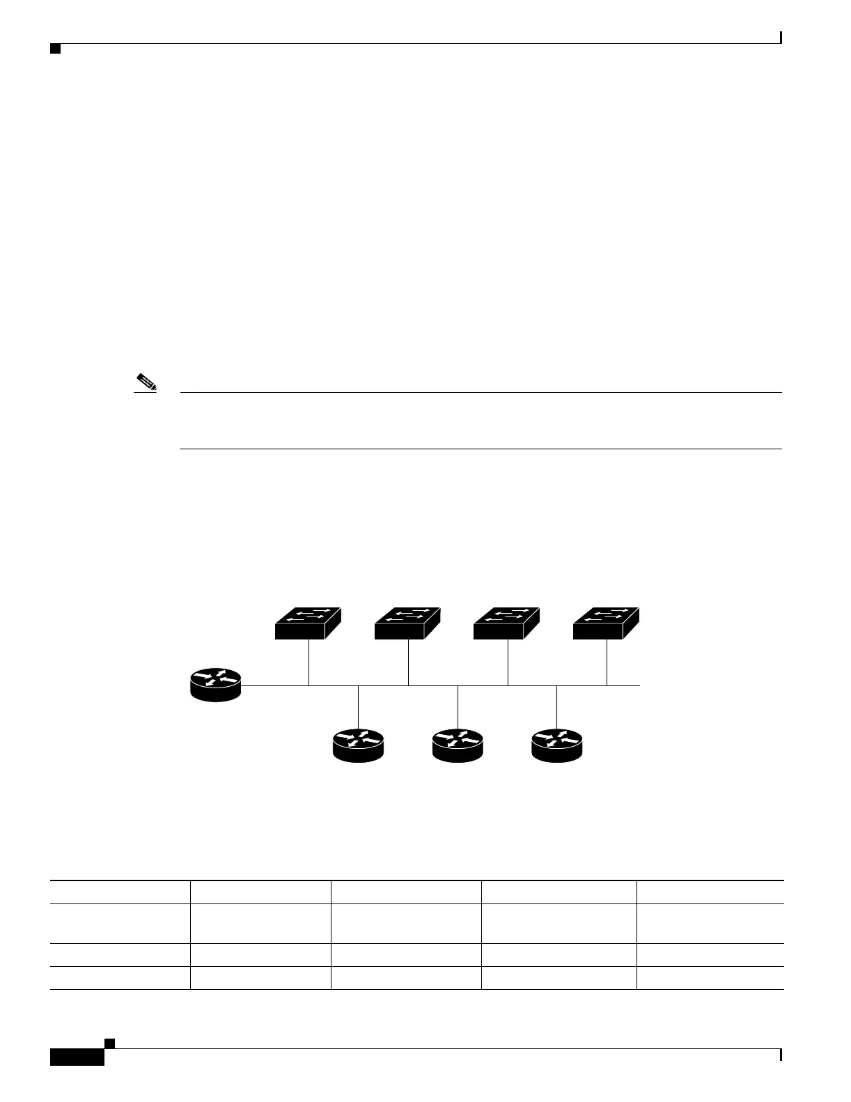
Figure 4-3 shows a sample network for retrieving IP information by using DHCP-based autoconfiguration.
Figure 4-3 DHCP-Based Autoconfiguration Network Example
Table 4-2 shows the configuration of the reserved leases on the DHCP server or the DHCP server feature
running on your switch.
Switch 1
00e0.9f1e.2001
Cisco router
49066
Switch 2
00e0.9f1e.2002
Switch 3
00e0.9f1e.2003
DHCP server DNS server TFTP server
(maritsu)
10.0.0.1
10.0.0.10
10.0.0.2 10.0.0.3
Switch 4
00e0.9f1e.2004
Table 4-2 DHCP Server Configuration
Switch-1 Switch-2 Switch-3 Switch-4
Binding key
(hardware address)
00e0.9f1e.2001 00e0.9f1e.2002 00e0.9f1e.2003 00e0.9f1e.2004
IP address 10.0.0.21 10.0.0.22 10.0.0.23 10.0.0.24
Subnet mask 255.255.255.0 255.255.255.0 255.255.255.0 255.255.255.0

 Loading...
