•
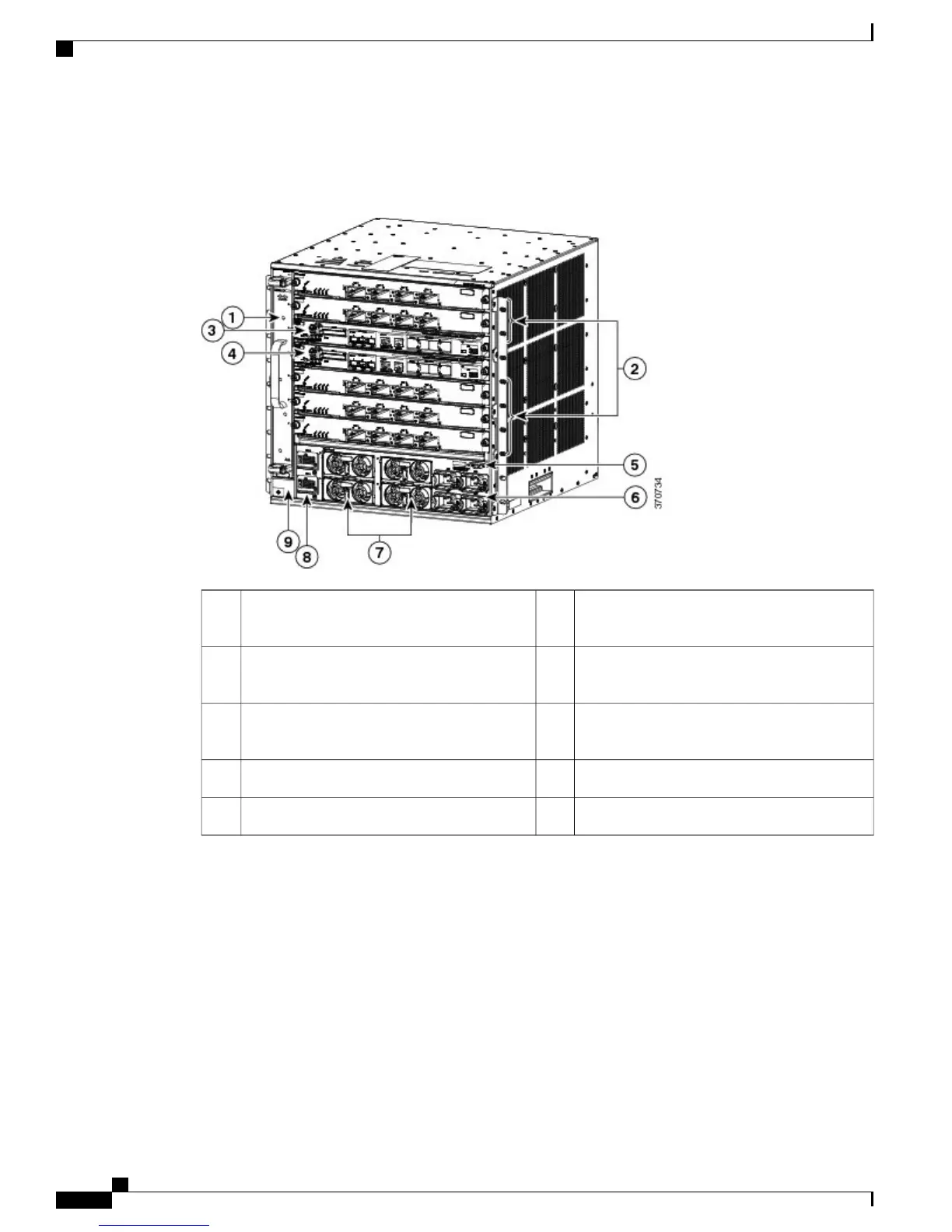
System ground connector
Figure 1: Cisco Catalyst 6807-XL Front Panel
Power entry modules (PEMs), labeled AC1
through AC4
6Fan tray1
Power supply modules (PSMs), labeled 1
through 4
7Module slots (line cards) 1, 2, 5,6, and 72
Power supply converter (PSC), labeled PSC1
and PSC2
8Supervisor engine slot3
System ground connector9Supervisor engine slot4
System On/Off switch5
Chassis
The Cisco Catalyst 6807-XL switch chassis has seven horizontal slots, of which five are module slots and
two are supervisor engine slots.
Related Topics
Rack-Mounting the Chassis, on page 37
Environmental Specifications, on page 62
Physical Specifications, on page 61
Cisco Catalyst 6807-XL Switch Hardware Installation Guide
2 OL-30656-01
Product Overview
Chassis
 Loading...


