• Redundancy—The PSCs share power when both are installed. If one PSC fails, the chassis will still be
operational.
Related Topics
Removing and Installing the Power Supply Converter, on page 57
Power Supply Converter LEDs, on page 10
LEDs
Use the switch LEDs to monitor switch activity and performance.
For information about module and supervisor engine LEDs, refer to the Catalyst 6500 Ethernet Module
Installation Guide and the Catalyst 6500 Series Switch Supervisor Engine Guide available on Cisco.com.
Fan Tray LED
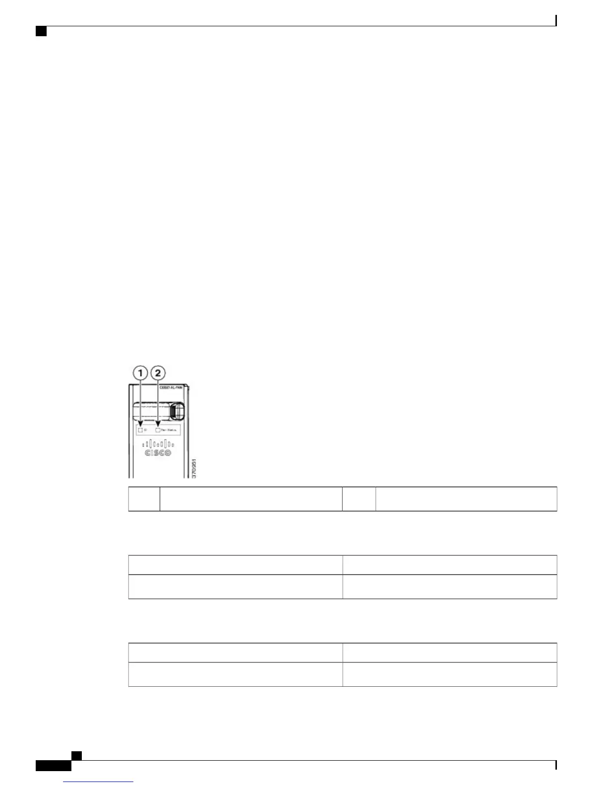
The fan tray includes an ID LED and a Fan Status LED, as shown in the following figure. The different states
of the LEDs are described in the following tables.
Figure 2: Fan Tray LED Locations
Fan Status2ID1
Table 3: Fan ID LED and Description
MeaningLED Color
Identifies the fan module in the chassisBlue
Table 4: Fan Status LEDs and Descriptions
MeaningLED Color
Fan is operating normallyGreen
Cisco Catalyst 6807-XL Switch Hardware Installation Guide
8 OL-30656-01
Product Overview
LEDs
 Loading...


