rack-mount screws. The clip nuts or cage nuts are not included as part of the accessory kit; you must
obtain them on your own.
• Rack-mount shelf kit—This kit is used to support the weight of the chassis while you secure the chassis
L brackets to the rack enclosure. It consists of two shelf brackets and a crossbar bracket.
• Two 9-slot cable management guides—The cable guides can be installed on the front of the chassis
using the same sets of screws that secure the chassis rack-mount brackets to the rack posts.
• Power supply and module blank panels—The power supply and module blank panels must be installed
on any unused power supply bays or module slots to maintain chassis airflow and EMI shielding.
•
Right-angled grounding lug and disposable ESD wrist strap and clip.
•
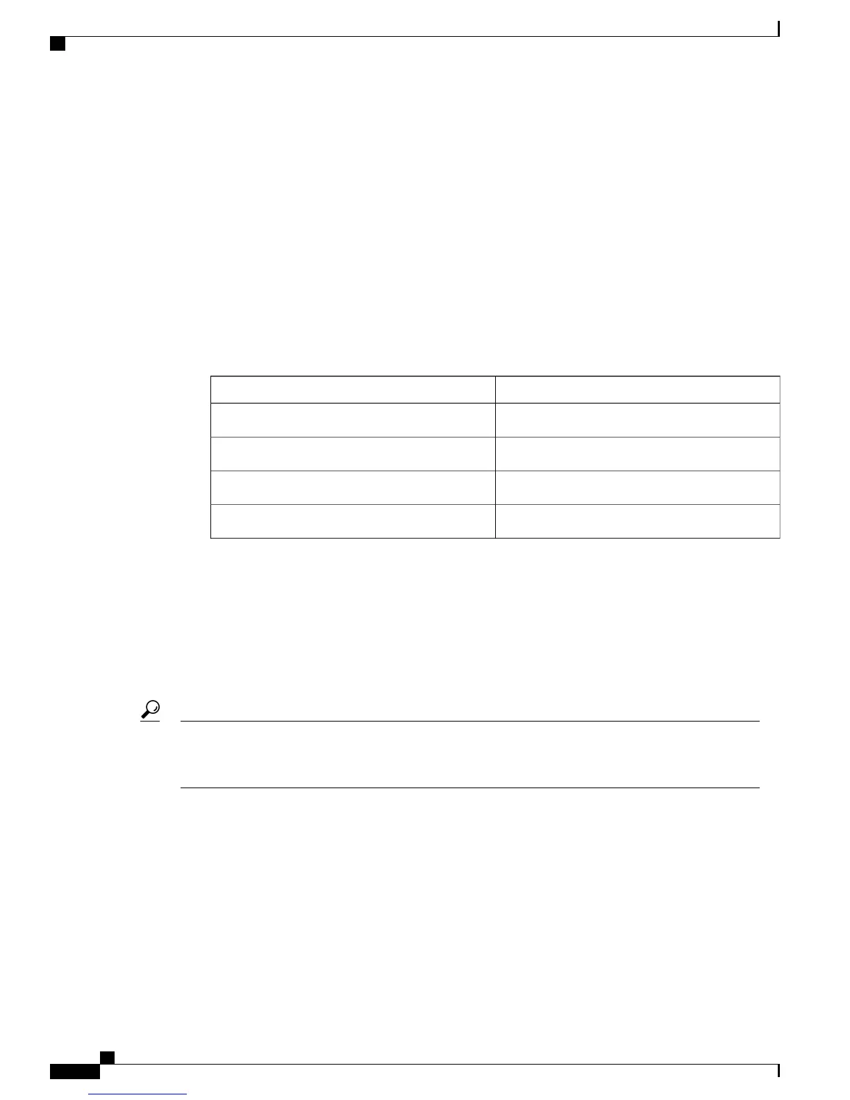
Screws
Table 11: Types of Screws Shipped with the Accessory Kit
QuantityType
2412-24 x 0.75mm
2410-32 x 0.75mm
2M3 x 0.5 x 8mm
2M4 x 8mm
Related Topics
Rack-Mounting Guidelines, on page 24
Unpacking the Switch
Do not discard the shipping container when you unpack the switch. Flatten the shipping cartons and store
them with the pallet. You will require these containers if you have to move or ship the switch in the future.
For repacking instructions, see Repacking the Switch, on page 99.
Tip
To check the contents of the shipping container, perform the following:
•
Check the contents of the accessory kit. Verify that you have received all the listed equipment, including
any optional equipment you may have ordered, such as, network interface cables, transceivers, or special
connectors.
•
Check the modules in each slot. Ensure that the configuration matches the packing list and that all of
the specified interfaces are included.
Cisco Catalyst 6807-XL Switch Hardware Installation Guide
32 OL-30656-01
Installing the Switch
Unpacking the Switch
 Loading...


