MeaningLED Color
One or more individual fans have failedRed
Related Topics
Removing and Installing the Fan Tray, on page 54
Troubleshooting the Fan Tray, on page 105
Fan Tray, on page 4
Air Flow, on page 15
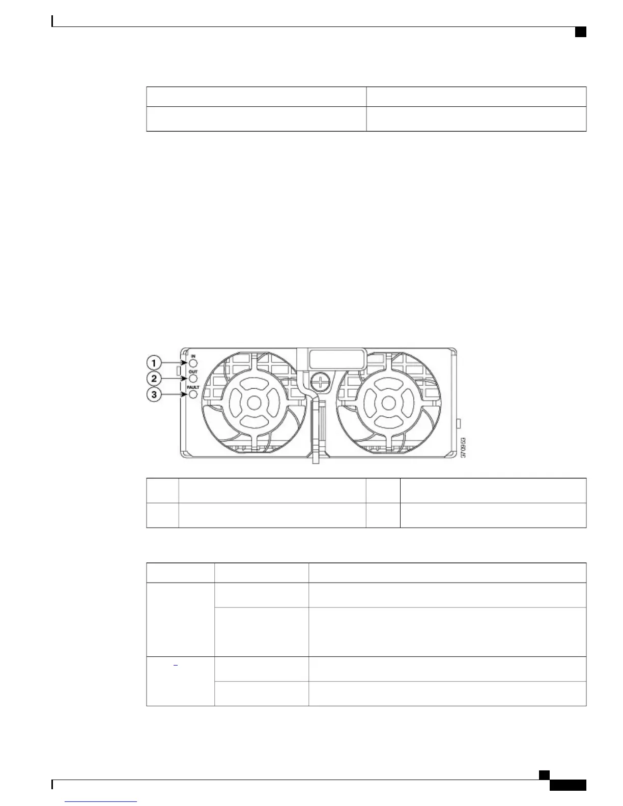
Power Supply Module LEDs
The PSM includes an IN, OUT, and FAULT LED, as shown in the following figure. The different states of
the LEDs are described in the following tables.
Figure 3: Power Supply Module LED Locations
FAULT3IN1
OUT2
PSM LEDs and Descriptions
MeaningLED ColorLED
Input AC is present and within regulation rangeGreenIN
Input AC is present but not within regulation range or AC power
was just disconnected and the power supply internal circuitry is still
charged
Green (blinking)
Power output is OKGreenOUT
4
Output is in a power limit or over current conditionGreen (blinking)
Cisco Catalyst 6807-XL Switch Hardware Installation Guide
OL-30656-01 9
Product Overview
LEDs
 Loading...


