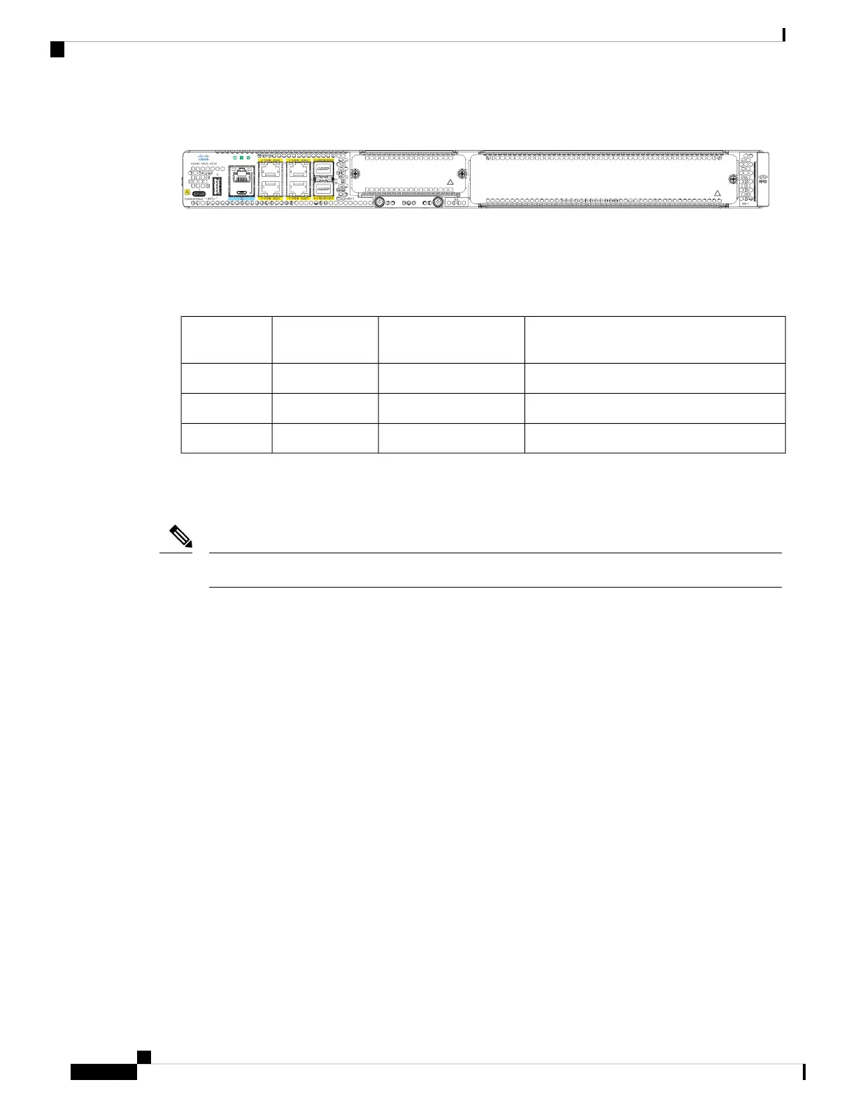
Figure 11:
In all cases, the device designates its interfaces using a 3-tuple notation that lists the slot, bay, and port. The
3-tuple value is zero based. An example of a 3-tuple is 0/1/2. This refers to slot 0, the second bay in slot 0
(the first bay is 0 so the second bay is 1), and the third port in bay 1. See the following table for more examples.
Table 7: Slot, Subslot-Bay and Port Numbering
PortBaySlot3-Tuple
Example
3rd2nd00/1/2
2nd1st00/0/1
2nd2nd11/1/1
• Slots and bays are numbered from the left to the right, and from the top to the bottom.
• The two USB ports are named USB0 and USB1. They do not have slot or bay numbers.
USB0 and USB1 can be used to insert flash drives.
Note
Slot Numbering
Slots are numbered 0, 1, and 2.
About Slot 0
The following are the main features of Slot 0:
• Slot 0 is reserved for integrated ports and NIMs, it can be used for either SM or NIM.
• NIMs are designated by the number of the first slot that they occupy. A double-wide SM occupies two
slots, but its designation is only the left-most slot number.
• The ten GE ports (or native interface ports) always reside in slot 0 and bay 0. The ports are called
Gigabitethernet 0/0/0, Gigabitethernet 0/0/1, Gigabitethernet 0/0/2, and Gigabitethernet 0/0/3 (up to as
many ports supported on the particular router).
Subslot and Bay Numbering
• Integrated devices, also known as integrated ports or FPGEs, and NIMs reside in a fixed section of bay
0.
• Motherboard NIMs bays start at bay 1 because the integrated devices and integrated NIMs take up bay
0.
Hardware Installation Guide for Cisco Catalyst 8300 Series Edge Platforms
14
Overview
Slot Numbering

 Loading...