Step 4 Tighten the screws securing the fan tray in the chassis.
Remove the PoE Converter Power Supply
To remove the PoE converter power supply, follow these steps:
Step 1 Remove the fan tray from the device.
Step 2 Loosen the screws securing the fan tray in the chassis.
Step 3 Remove the fantray from the device.
Step 4 Loosen the two screws securing the POE supply in the device.
Step 5 Rotate the PoE latch and pull the supply out of the slot.
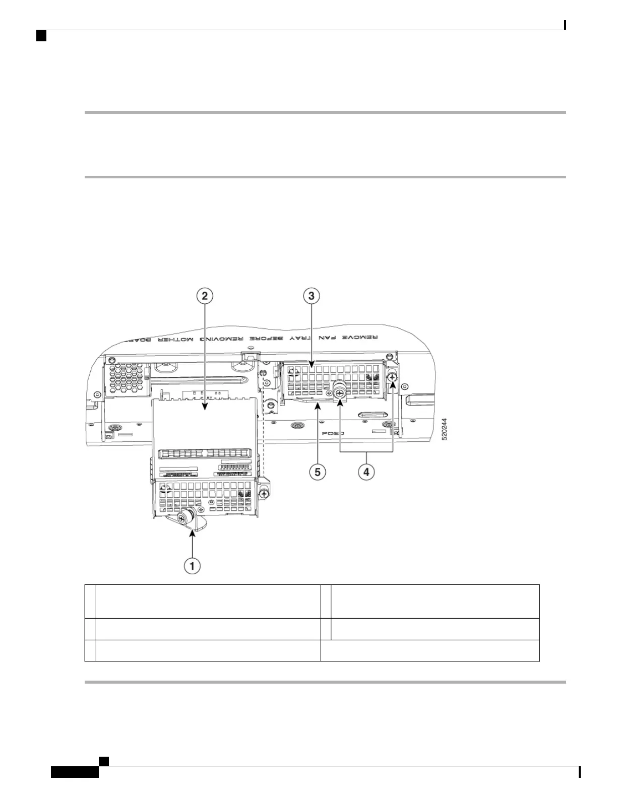
Figure 63: Remove the PoE Converter Power Supply
PoE converter module being installed in PoE slot
1
2Latch to secure module (shown open).1
Screws to secure PoE module to the chassis.4PoE converter module installed in PoE slot 03
Latch to secure PoE converter module (shown closed).5
Hardware Installation Guide for Cisco Catalyst 8300 Series Edge Platforms
84
Install Internal Components and Field Replaceable Units
Remove the PoE Converter Power Supply

 Loading...