This section shows the location of the PoE converter power supply slots located behind fan tray.
Remove the PoE Power Supply Slot Filler
To remove a PoE power supply filler, perform these steps:
Step 1 Loosen the screws securing the fan tray in the chassis.
Step 2 Remove the fan tray from the device.
Step 3 Loosen the screw securing the filler panel in the device.
Step 4 Pull on the screw and rotate the filler panel out of the slot.
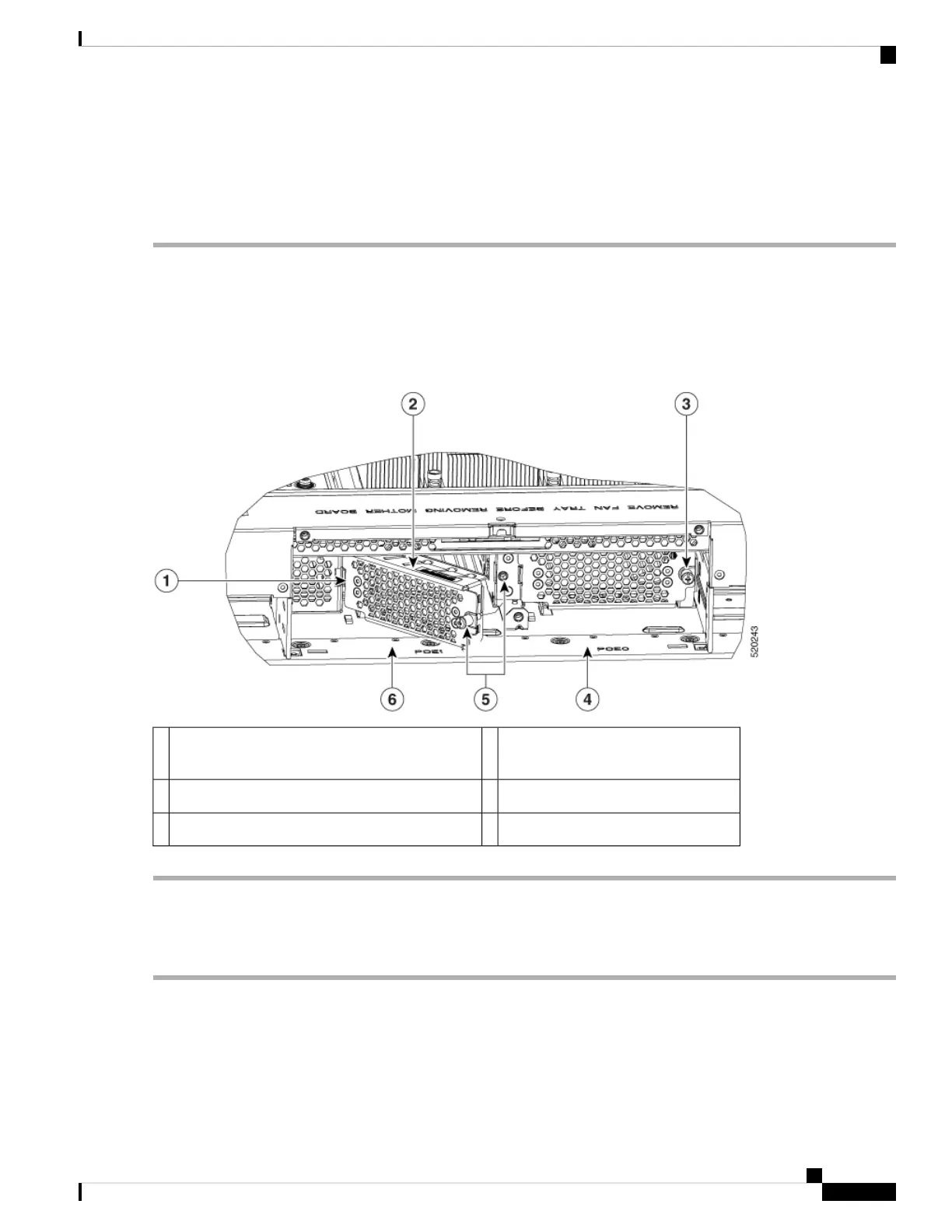
Figure 62: Remove PoE Power Supply Slot Fillers
POE filler being installed in PoE slot
1
2Install tab slot on the chassis1
PoE slot 04PoE filler shown installed in PoE slot 03
PoE slot 16Rotate to secure screw into securing nut in chassis5
Install the PoE Power Supply Slot Filler
To install a PoE power supply slot filler, perform these steps:
Step 1 Install the tab on the left side of the filler panel into the slot in the chassis.
Step 2 Tighten the screw to secure the filler panel in the chassis.
Step 3 Install the fan tray from the device.
Hardware Installation Guide for Cisco Catalyst 8300 Series Edge Platforms
83
Install Internal Components and Field Replaceable Units
Remove the PoE Power Supply Slot Filler

 Loading...