ID-FLX Lite & Telecom Global Guide
82
7.2.3 Modem connection
PC can be connected to the controller also remotely via modems. Either an analog, GSM, ISDN or 3G modem
must be connected to the RS232 interface, see Group: Communication settings on page 103: COM1 Mode
has to be set to MODEM.
Note: RF modem communication is also possible between controller and remote display.
Note: In case of controller and remote display RF modem should be connected with serial cable with only three
connected pins Rx, Tx and GND. In other case could be blocked communication between modem and
controller.
7.3 Modbus connection
Modbus protocol was implemented into the controllers to allow design of own supervision software offering
customer or to use ComAp SCADA software.
To learn more about Modbus interface see the training videos on Basic Modbus I and Basic Modbus II.
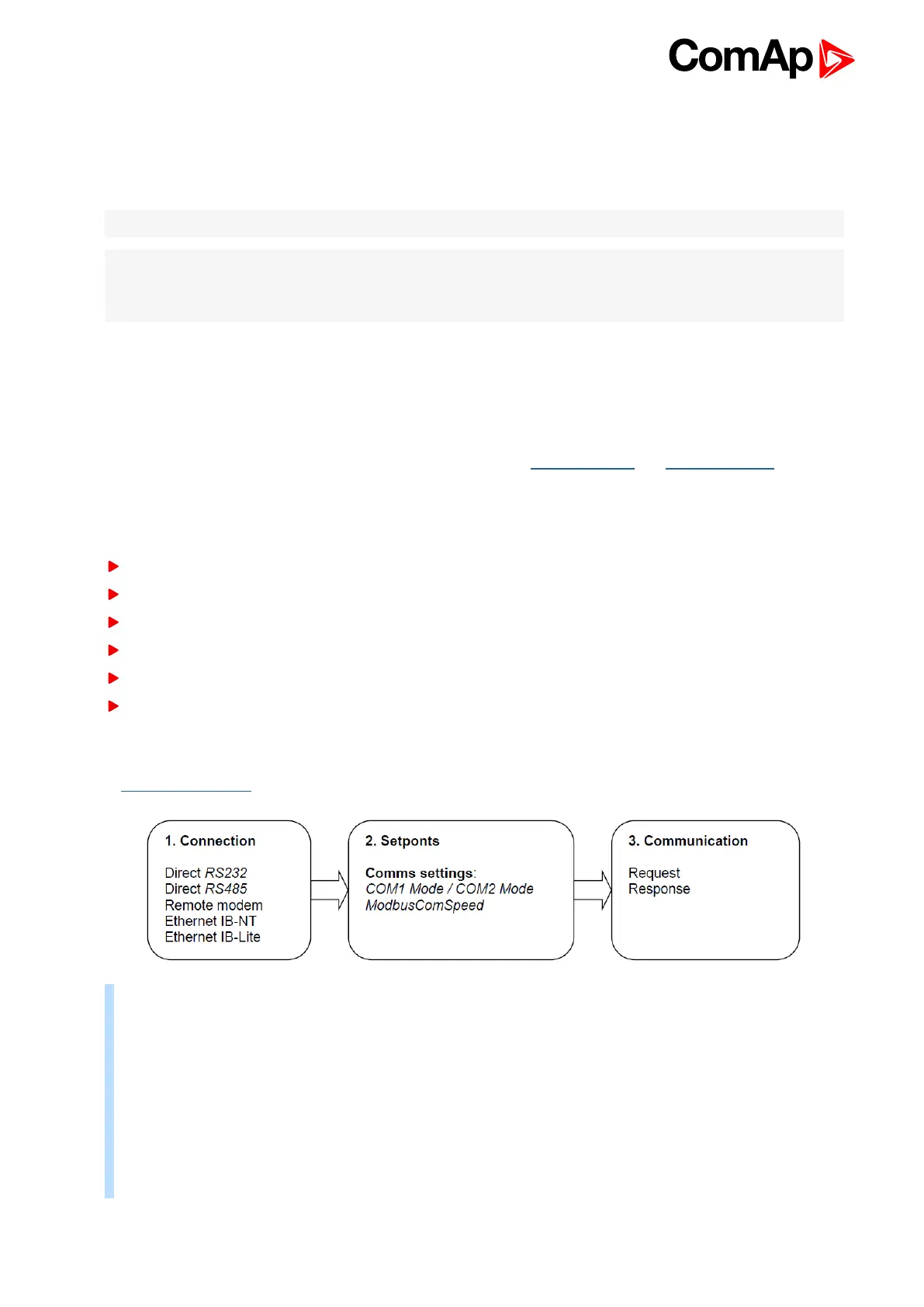
7.3.1 Modbus step by step
Use LiteEdit: Controller->Generate Cfg image->Modbus registers command to get registers list.
9600 bps, 8 data bits, 1 stop bit, no parity
Transfer mode RTU
Function 3 (Read Multiply Registers) max length of block is 127 registers
Function 6 (Write Single Register)
Function 16 (Write Multiply Registers) max 16 registers
The response to an incoming message is sent with minimum 4.096 ms delay after message reception
The complete description of Modbus communication protocol can be found in Modbus Protocol Reference
Guide PI-MBUS-300 and Open Modbus Specification Release 1.0. Both documents are available from web site
at www.modicon.com .
Example: Request: 01 03 00 35 00 03 15 C5
01 = Controller address
03 = Modbus function code (Read Multiple Registers)
00 35
= Register address: Register number (40054) – 40001 = 53 DEC => 35 HEX IL-NT
Register address: Register number (40061) – 40001 = 60 DEC => 3C HEX IC-NT
00 03
= Number of registers (40054 – Oil press, 40055 – Engine temp, 40056 – Fuel level)
= 3 DEC = > 03 HEX
C5 15 = CRC (write LSB MSB !)

 Loading...


