STEERING
9
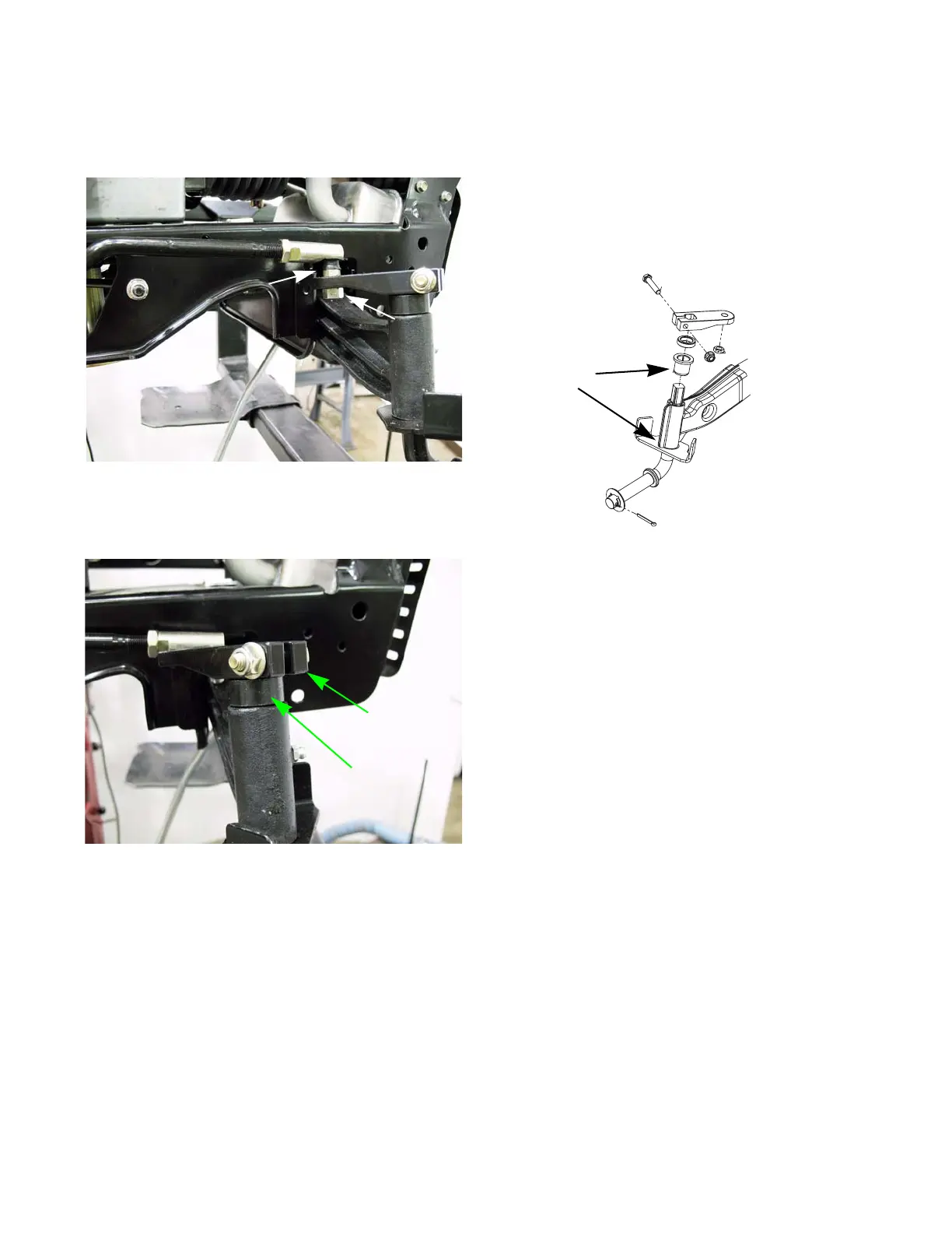
4. Remove the nut holding the drag link to the
steering block using a 1/2” and 9/16” wrench.
See Figure 3.6.
5. Support the axle and remove the steering block
using two 1/2” wrenches. See Figure 3.7.
NOTE: The SLT models do not have a spacer.
Figure 3.6
1/2” wrench
9/16” wrench
Figure 3.7
Steering block
Spacer
6. Remove the spacer and lower the axle out of the
pivot bar.
NOTE: Starting in the 2010 season, some trac-
tors will be equipped with a stamped pivot bar.
These tractors will have plastic bushing where
the axle rides inside the pivot bar.
See Figure 3.8.
NOTE: The procedure to remove this axle is the
same as previously described. When installing
the axle, install new upper and lower bushings.
7. Install the axle by following the previous steps in
reverse order.
8. Perform a wheel alignment by following the
steps described in the steering alignment sec-
tion of this chapter.
9. Test run the tractor in a safe area before return-
ing it to service.
Figure 3.8
Bushings
 Loading...


