BODY PANELS
21
2d. Lift the battery tray out of the tractor.
CAUTION: When reinstalling a battery in this
tractor, use only the original type of battery.
The negative terminal must
go toward the rear of
the tractor.
NOTE: It is not necessary to remove the seat
bracket when removing the fenders.
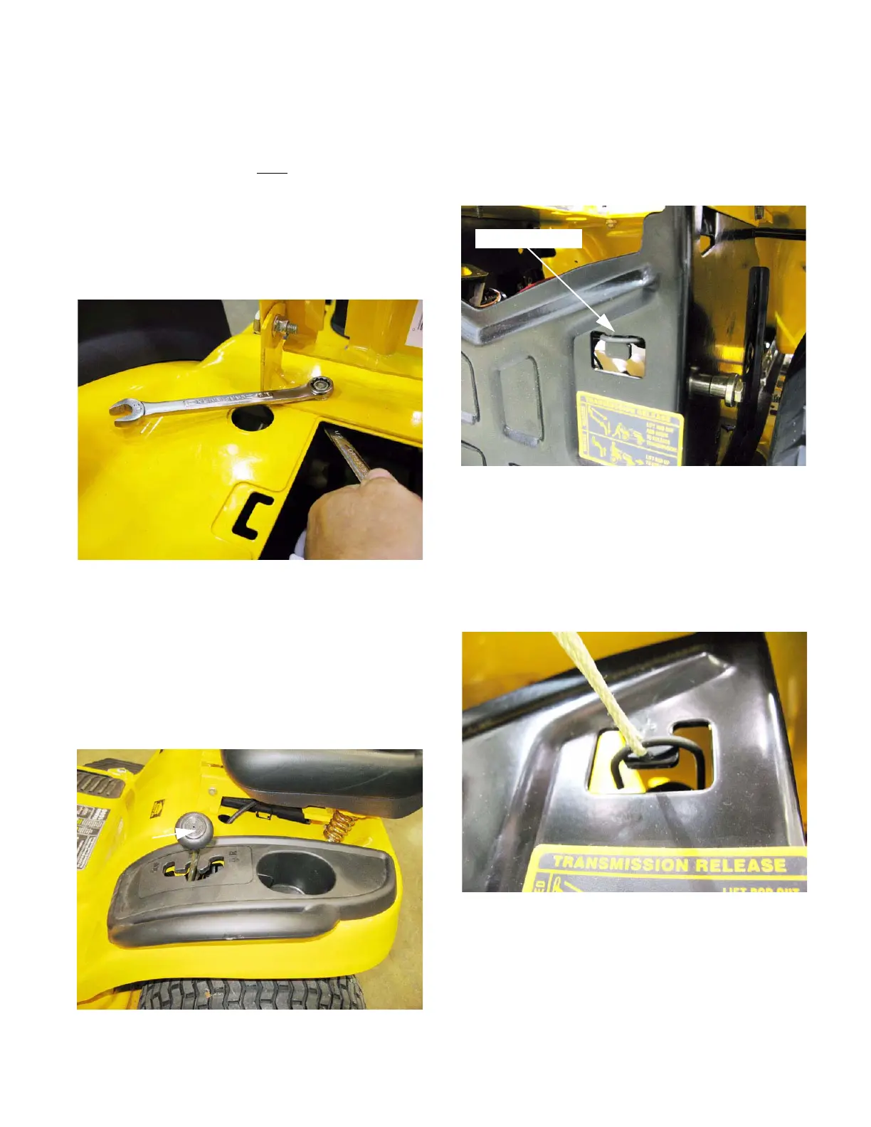
2e. The seat bracket may be removed using a
pair of 1/2” wrenches. See Figure 4.21.
NOTE: New production units will use self tap-
ping screws instead of a nut and bolt.
3. Remove the grips from the fender-mounted con-
trol levers.
3a. Pull the shift knob off of the forward-neutral-
reverse lever on CVT-equipped tractors.
See Figure 4.22.
Figure 4.21
Figure 4.22
lever
F-N-R
3b. If the tractor has a deck lift assist spring,
remove the deck or lift the mower deck to
the highest position and support it with wood
blocks. See Figure 4.23.
NOTE: Tractors equipped with the 38” deck and
42” timed-blade R-deck will not have lift assist
springs.
3c. Unhook and gently release the lift assist
spring from the back of the tractor frame.
See Figure 4.24.
Figure 4.23
Lift assist spring
Figure 4.24
 Loading...


