HEADLIGHT VOLTAGE INSPECTION
● Remove the front cover. ( 3-5)
·Check voltage with the headlight coupler connected.
● After starting the engine, place the dimmer switch to
HI and check the voltage between the blue (+) and
green (-) wires of the headlight coupler.
·Measurement is performed in AC area.
CONTROL VOLTAGE : 12.6~13.6V/5,000rpm
● If voltage is incorrect, check the regulator/rectifier.
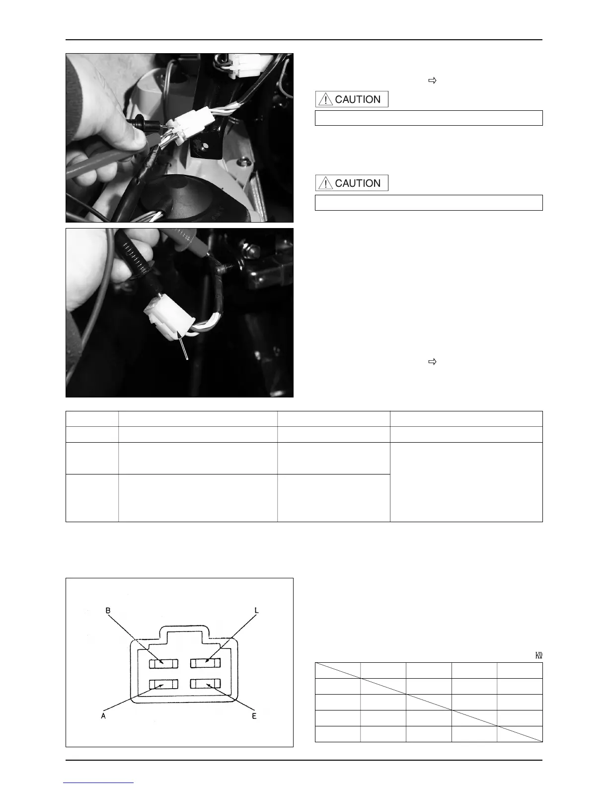
REGULATOR/RECTIFIER INSPECTION
HARNESS CIRCUIT INSPECTION
● Remove the front cover. ( 3-5 )
● Remove the 4P coupler of the regulator/rectifier and
inspect the wiring circuit in the main harness side
terminal.
REGULATOR/RECTIFIER INSPECTION
● If the inspection of the harness side proves to be
satisfactory, check the regulator/rectifier coupler for
faulty connection, and measure the resistance between
the terminals of the regulator/rectifier.
13-6
CHARGING SYSTEM/A.C.GENERATOR
ITEM
BATTERY WIRE
CHARGING
COIL
LIGHTING
COIL
Voltage between red “⊕” and green “⊖”.
※ Resistance between white wire and
earth wires. Disconnect the starter.
※ Resistance between yellow wire and
earth wires. Disconnect dimmer
switch connection
Damaged, disconnected main fuse/harness.
AC generator (charging, lighting coil
coupler connection damage) resister(
6.7Ω
5W) headlight lighting circuit.
There must be battery voltage.
0.4~1.0Ω(20℃)
0.2~0.8Ω(20℃)
MEASUREMENT LOCATION LEVEL
AREAS OF INSPECTION IF INCORRECT
ALB E
A ∞ 3-50 ∞
L ∞∞5-100
B ∞∞ ∞
E ∞ 5-100 ∞
Inspect ※ part after at least 10 minutes later.
RESISTANCE VALUE
Tester ⊕
Tester ⊖
(
20℃
) Unit :
(BATEERY TERMINAL)
TERMINAL ARRANGEMENT
(LAMP TERMINAL)
(EARTH TERMINAL)(CHARGING TERMINAL)
 Loading...