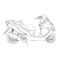
PULSE GENERATOR
·Inspect with the spark plug assembled and while
there is compression pressure.
● Remove the CDI unit. (
14-7 )
● Remove the coupler from the CDI unit and connect the
peak voltage adaptor to the pulse generator wire (blue/
yellow and green) of harness coupler.
● Operate the starter motor and measure the peak voltage
of the pulse generator coil.
CONTACT POINTS :
BLUE/YELLOW TERMINAL “
⊕⊕
”-BODY EARTH“
⊖⊖
”
PEAK VOLTAGE : OVER 1.5V
·When measuring voltage, do not touch the metal part
of the handle rod as there is the danger of receiving
an electric shock.
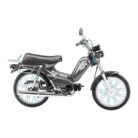
● Perform the following inspections if measured peak
voltage in the CDI unit coupler portion is abnormal.
● Disconnect the AC generator cord coupler and connect
the adaptor.
● In the same manner as with the unit coupler side,
measure peak voltage and compare with the first peak
voltage.
● When the measured value in the unit side is abnormal
and normal in the pulse generator side, the problem is
either incorrect coupler connection or disconnection of
the wire harness.
● When both measurements are abnormal, this indicates
a problem with the pulse generator. Refer to the
malfunction diagnosis are go through each step.
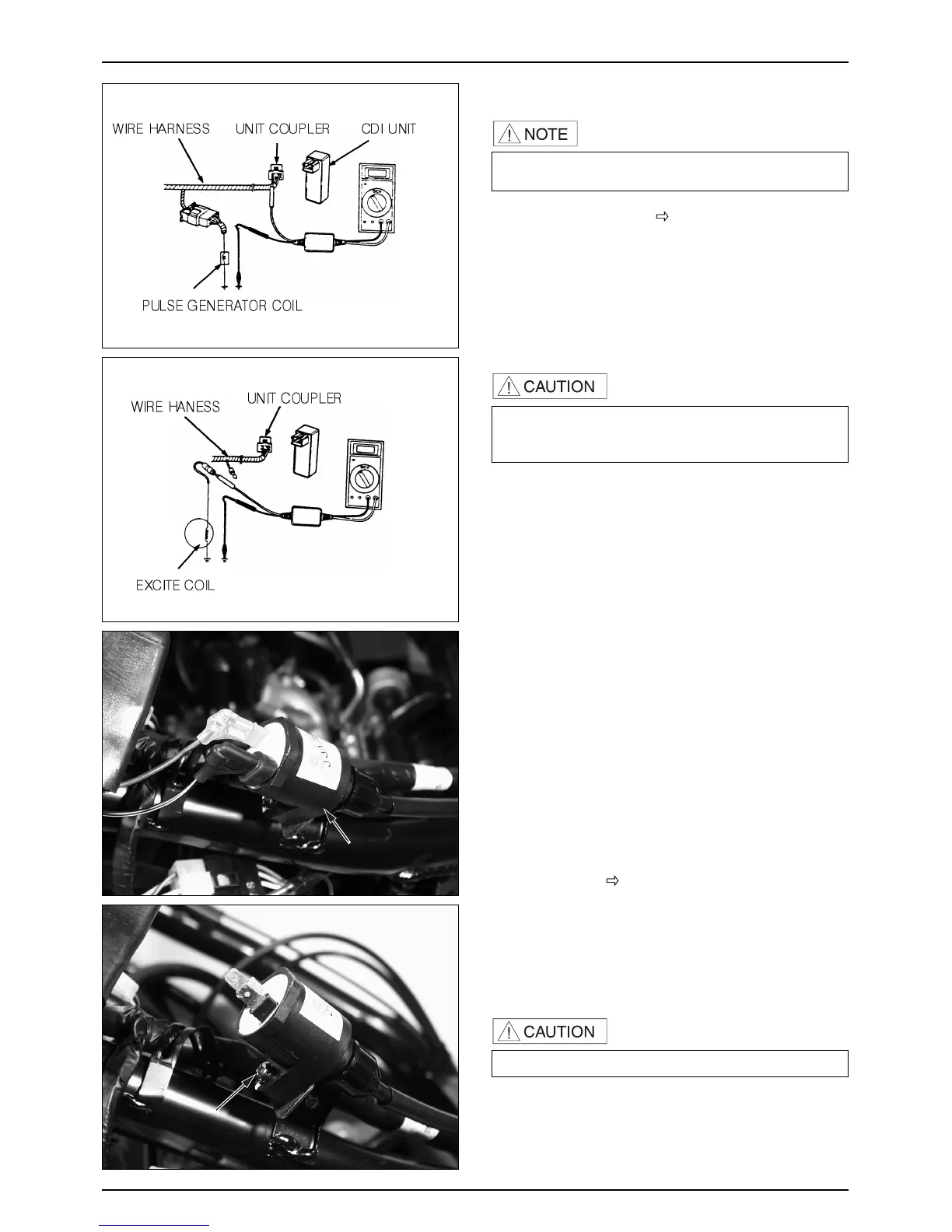
IGNITION COIL
REMOVAL/INSTALLATION
REMOVE
● Luggage box. ( 3-3 )
● Plug maintenance cover.
● Spark plug cap.
● Loosen the ignition coil fixing bolt.
● Disconnect the ignition coil wire.
● Remove the ignition coil.
● Install in the reverse order of removal.
·Arrange the cords in the right place.
 Loading...