Parameter
Number
617 Unit: V
Data type: uint16 Access type: Read/Write
P 9.5.2.10 T33 Current Dead Zone Scale
A non-zero value for the parameter enables the dead-zone function. The dead-zone band defines an area which could freeze the pointed
speed reference by scaled analog input signal, or ignore unexpected vibration at desired speed caused by disturbance of reference
signal. The bandwidth of dead zone is the double value of P 9.5.2.10 T33 Current Dead Zone Scale.
Default value: 0 Parameter type: Range (0–1000)
Parameter
Number
618 Unit: mA
Data type: uint16 Access type: Read/Write
Dead-zone function
l A non-zero value for the parameter Voltage/Current Dead Zone Scale enables the dead-zone function. The dead-zone band defines
an area which could freeze the pointed speed reference by scaled analog input signal, or ignore unexpected vibration at desired
speed caused by disturbance of reference signal.
l The bandwidth of dead zone is the double value of Voltage/Current Dead Zone Scale.
l Dead-zone band central point is the mid-value of High and Low value of the voltage or current.
l When Low Ref./feedb. Value is a negative value, and the parameter of AI minimum valueLow Voltage/Current set as 0, if the analog
input signal is lost (AI input value = 0), the motor runs at the value of Low Ref./feedb. Value without expectation. This would cause
uncertainty risk or danger. Therefore, the parameters of AI Low Voltage/Current should be set as a non-zero value, like 2 V or 4 mA.
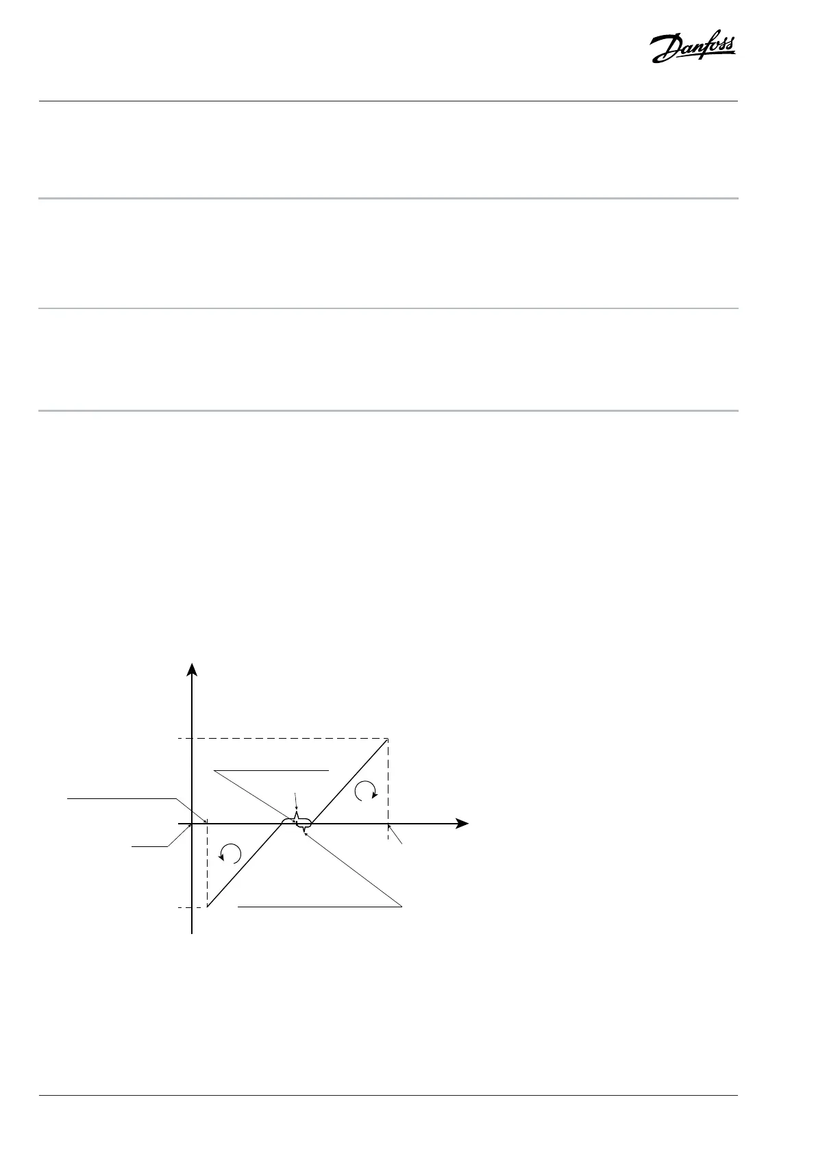
l The following illustration is an example of using T33 analog input (voltage mode, from 2 V to 10 V) for dead-zone function to control
motor running between the speed from -50 Hz to 50 Hz.
Reference
P 9.5.2.9 Voltage dead zone scale
(example value: 0.5 V)
Dead zone central point
(example value: 6 V)
(example value: 2 V)
P 9.5.2.2 T33 high voltage
(example value: 10 V)
P 9.5.2.7 T33 low ref./feedb. value
(example value: -50 Hz)
P 9.5.2.9 T33 high ref. /feedb. value
P 9.5.2.3 T33 low voltage
0 V
0 Hz
Dead zone band
Reverse
Forward
Figure 86: Dead-zone Function Example
The typcial parameter settings for the examples are shown in the following tables.
252 | Danfoss A/S © 2024.03 AB413939445838en-000301 / 130R1254
Application Guide | iC2-Micro Frequency Converters

 Loading...


