Application Guide | iC2-Micro Frequency Converters
6 RS485 Configurations
6.1 RS485 Installation and Set up
6.1.1 Introduction
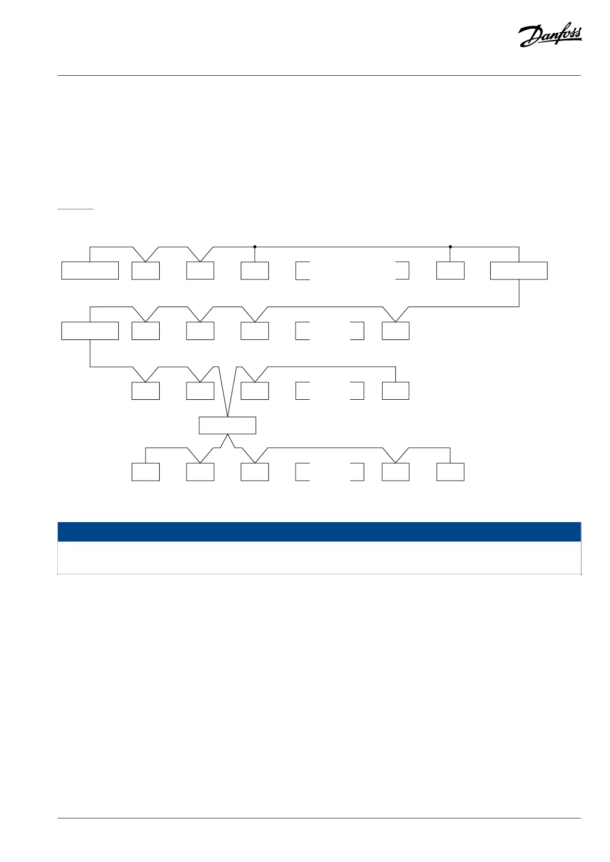
RS485 is a 2-wire bus interface compatible with multi-drop network topology. The nodes can be connected as a bus, or via drop cables
from a common trunk line. A total of 32 nodes can be connected to 1 network segment. Repeaters divide network segments, see the
Figure 51.
Figure 51: RS485 Bus Interface
NOTICE
Each repeater functions as a node within the segment in which it is installed. Each node connected within a given network must
have a unique node address across all segments.
Terminate each segment at both ends, using either the termination switch (S801) of the drives or a biased termination resistor network.
Always use shielded twisted pair (STP) cable for bus cabling and follow good common installation practice.
Low-impedance ground connection of the shield at every node is important, including at high frequencies. Thus, connect a large surface
of the shield to ground, for example with a cable clamp or a conductive cable gland. Sometimes, it is necessary to apply potential-
equalizing cables to maintain the same ground potential throughout the network, particularly in installations with long cables.
To prevent impedance mismatch, use the same type of cable throughout the entire network. When connecting a motor to the drive,
always use shielded motor cable.
Danfoss A/S © 2024.03 AB413939445838en-000301 / 130R1254 | 73

 Loading...


