Application Guide | iC2-Micro Frequency Converters
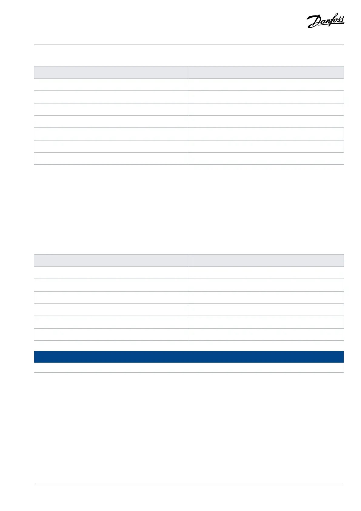
Table 39: Query
Field name Example (hex)
Follower address 01 (drive address)
Function 01 (read coils)
Starting address HI 00
Starting address LO 20 (32 decimals) coil 33
Number of points HI 00
Number of points LO 10 (16 decimals)
Error check (CRC) –
Response
The coil status in the response telegram is packed as 1 coil per bit of the data field. Status is indicated as: 1 = ON; 0 = OFF. The lsb of the
1st data byte contains the coil addressed in the query. The other coils follow toward the high-order end of this byte, and from low order
to high order in subsequent bytes.
If the returned coil quantity is not a multiple of 8, the remaining bits in the final data byte are padded with values 0 (toward the high-
order end of the byte). The byte count field specifies the number of complete bytes of data.
Table 40: Response
Field name Example (hex)
Follower address 01 (drive address)
Function 01 (read coils)
Byte count 02 (2 bytes of data)
Data (coils 40–33) 07
Data (coils 48–41) 06 (STW = 0607hex)
Error check (CRC) –
NOTICE
Coils and registers are addressed explicitly with an offset of -1 in Modbus. For example, coil 33 is addressed as coil 32.
6.1.7.6.2 Read Holding Registers (03 hex)
Description
This function reads the contents of holding registers in the follower.
Query
The query telegram specifies the starting register and quantity of registers to be read. Register addresses start at 0, that is, registers 1–4
are addressed as 0–3.
Example: Read P 5.5.3.3 Reference Maximum, register 3029. The parameter number is 303.
Danfoss A/S © 2024.03 AB413939445838en-000301 / 130R1254 | 91

 Loading...


