Table 7: Control Panel Elements Description (continued)
Legend Name of element Description
7 RUN LED The indicator has the following states:
• On: The drive is in normal operation.
• Off: The drive has stopped.
• Flash: The indicator is in this state when:
- In the motor-stopping process (ramp down).
- The drive received a RUN command, but no frequency output.
8 Run Starts the operation of the drive.
9 REM/LOC Toggles the drive between remote and local operation.
10 Back Navigates to previously viewed screen or a menu level above the current menu.
11 Drive Status Indica-
tors
The related LEDs indicate the status of the drive.
• [WARN]: A steady yellow light indicates a warning.
• [READY]: A steady green light indicates that the drive is ready.
• [FAULT]: A flashing red light indicates a fault.
3.2.6 Control Panel 2.0 OP2 Basic Configurations
3.2.6.1 Overview
Basic configurations of the control panel include:
l Readout status of the motor and the drive which includes warnings and faults.
l Navigate to the menus in order to view or change parameter settings for the drive.
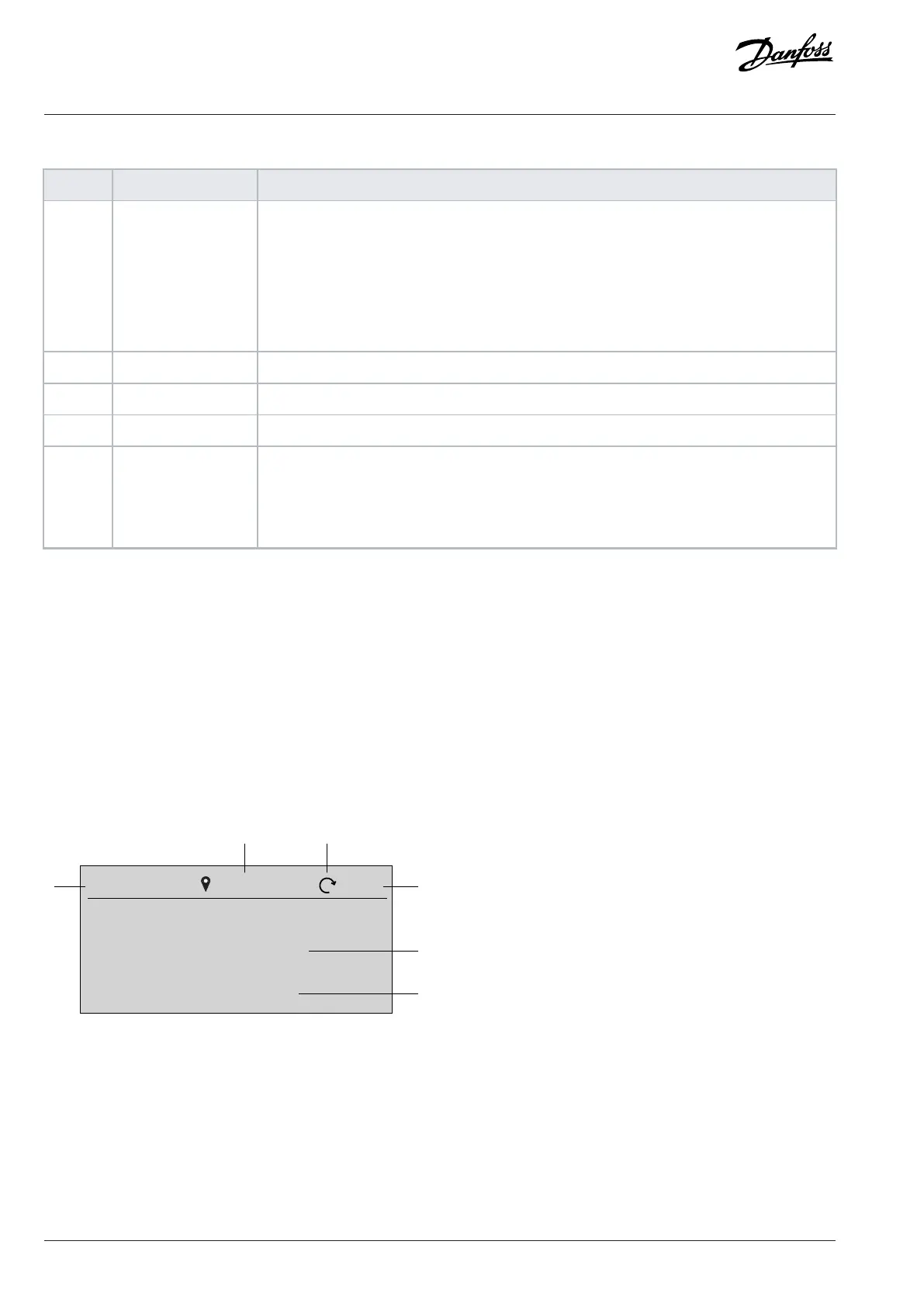
3.2.6.2 Understanding Readout Screens
When the drive is in ready state, the control panel 2.0 OP2 display shows the Home screen. By default, as a factory setting, the Home
screen is shown as follows.
Figure 10: Home Screen
The following are the legends and description of the Home screen.
30 | Danfoss A/S © 2024.03 AB413939445838en-000301 / 130R1254
Application Guide | iC2-Micro Frequency Converters

 Loading...


