The endpoints P1 and P2 are defined in the Table 21 depending on the choice of input.
Table 21: P1 and P2 Endpoints
Input AI 33 voltage mode AI 34 voltage mode AI 34 current mode Pulse input 18
P1=(Minimum input value, minimum reference value)
Minimum reference
value
P 9.5.2.7 T33 Low Ref./
Feedb. Value
P 9.5.3.7 T34 Low Ref./
Feedb. Value
P 9.5.3.7 T34 Low Ref./
Feedb. Value
P 9.4.4.4 T18 Low Ref./
Feedb. Value
Minimum input value P 9.5.2.3 T33 Low
Voltage
P 9.5.3.3 T34 Low
Voltage
P 9.5.3.5 T34 Low
Current
P 9.4.4.2 T18 Low
Frequency
P2=(Maximum input value, maximum reference value)
Maximum reference
value
P 9.5.2.6 T33 High Ref./
Feedb. Value
P 9.5.3.6 T34 High Ref./
Feedb. Value
P 9.5.3.6 T34 High Ref./
Feedb. Value
P 9.4.4.3 T18 High Ref./
Feedb. Value
Maximum input value P 9.5.2.2 T33 High
Voltage
P 9.5.3.2 T34 High
Voltage
P 9.5.3.4 T34 High
Current
P 9.4.4.1 T18 High
Frequency
5.6.5 Dead Band Around Zero
Sometimes, the reference (in rare cases also the feedback) should have a dead band around 0 to ensure that the machine is stopped
when the reference is near 0.
To make the dead band active and to set the amount of dead band, do the following:
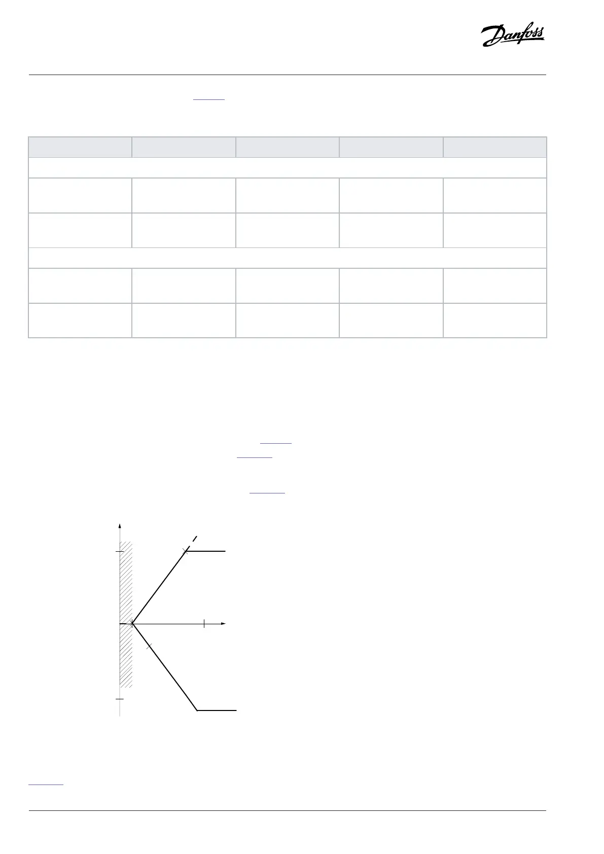
l Set either the minimum reference value (see the table in Table 21 for relevant parameter) or maximum reference value at 0. In other
words, either P1 or P2 must be on the X-axis in the Figure 48.
l Ensure that both points defining the scaling graph are in the same quadrant.
P1 or P2 defines the size of the dead band as shown in the Figure 48.
Resource output
[Hz] or “No unit”
Low reference/feedback
value
Figure 48: Size of Dead Band
Case 1: Positive reference with dead band, digital input to trigger reverse, part I
Figure 49 shows how reference input with limits inside minimum to maximum limits clamps.
70 | Danfoss A/S © 2024.03 AB413939445838en-000301 / 130R1254
Application Guide | iC2-Micro Frequency Converters

 Loading...


