© Danfoss | August 2018 AQ00000211 | 151
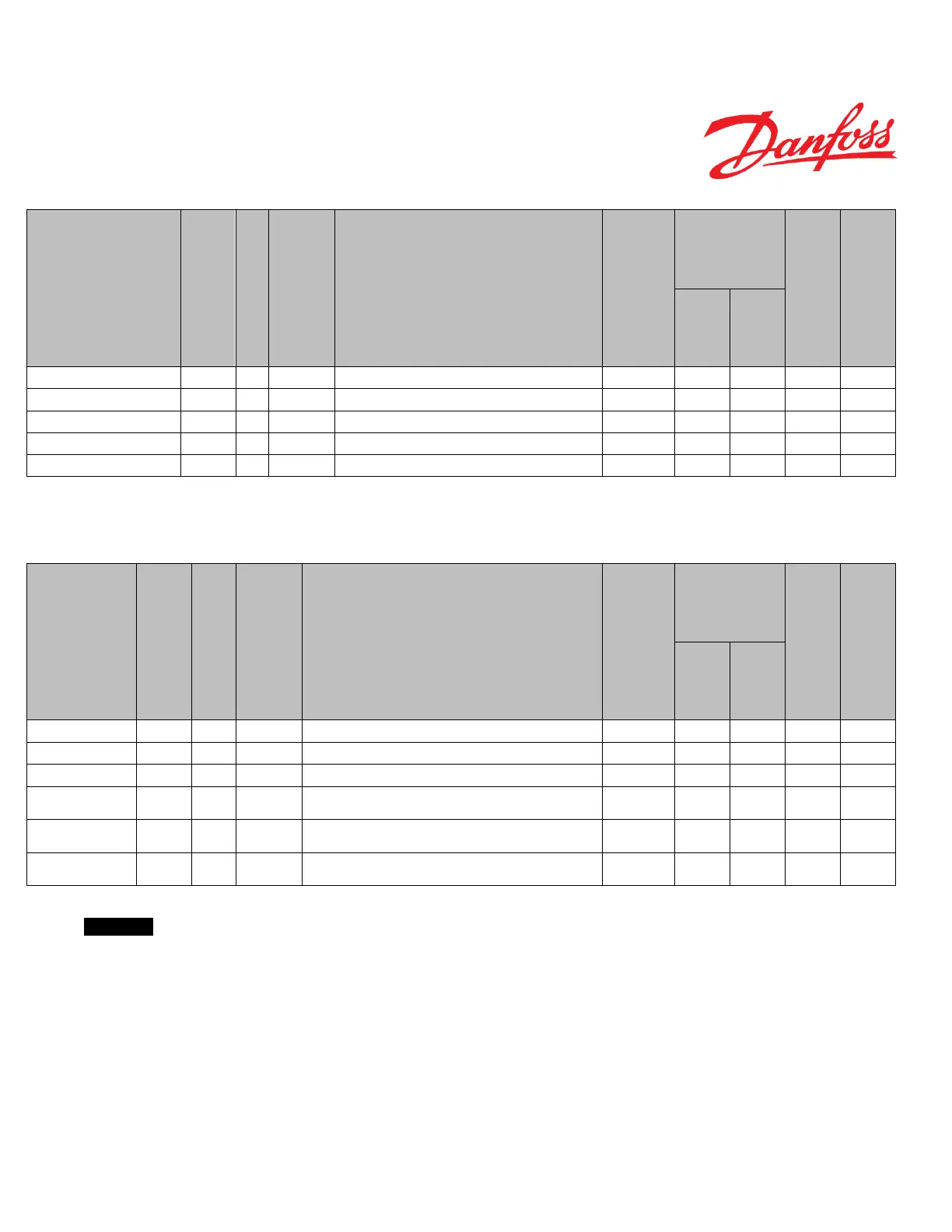
17.4.3 Valve Calibration
Name
Description of parameter
Range
Safety critical
parameters ‘S’
Max spool position, left P3162 S16 x10u Meter Spool left most position OEM, Dealer -1000 -300 -420
Max spool position, right P3164 S16 x10u Meter Spool right most position OEM, Dealer 300 1000 420
Closed loop dead-band edge, left P3166 S16 x10u Meter Spool closed loop dead-band edge, Left OEM, Dealer -300 0 -105
Closed loop dead-band edge, right P3168 S16 x10u Meter Spool closed loop dead-band edge, Right OEM, Dealer 0 300 105
Open loop dead-band edge offset P3170 S16 x10u Meter Spool open loop dead-band offset OEM, Dealer 0 150 25
Table 66
17.4.4 CAN WAS Calibration Data
Name
Description of parameter
Range
Safety critical
parameters ‘S’
WAS max left position
(CAN)
P3185 U16 mVolts Wheel angle sensor voltage output for leftmost position over CAN OEM, Dealer 0 5000 500
WAS max right position
(CAN)
P3187 U16 mVolts Wheel angle sensor voltage output for rightmost position over CAN OEM, Dealer 0 5000 4500
WAS neutral position
(CAN)
P3189 U16 mVolts Wheel angle sensor voltage output for neutral position over CAN OEM, Dealer 0 5000 2500
cylinder stroke volume
P3191 U16 ccm
Automatically adjusted cylinder stroke volume, for using CAN WAS,
found during WAS auto-calibration
OEM, Dealer 100 65535 65535
maximum steer angle to
P3193 U16 Deg
Automatically adjusted maximum steer angle to left side, for using CAN
WAS, found during WAS auto-calibration
OEM, Dealer 0 65535 65535
maximum steer angle to
P3195 U16 Deg
Automatically adjusted maximum steer angle to right side, for using CAN
WAS, found during WAS auto-calibration
OEM, Dealer 0 65535 65535
Table 67
Important
For CAN WAS calibration data sector, the following rules apply:
P3185 < P3187 < P3189 OR P3185 > P3187 > P3189
 Loading...


