178 | © Danfoss | August 2018 AQ00000211
Calibration procedure
The following steps describes a calibration procedure, which can be obtained or could be implemented in a service tool.
Refer Figure 69 for below steps.
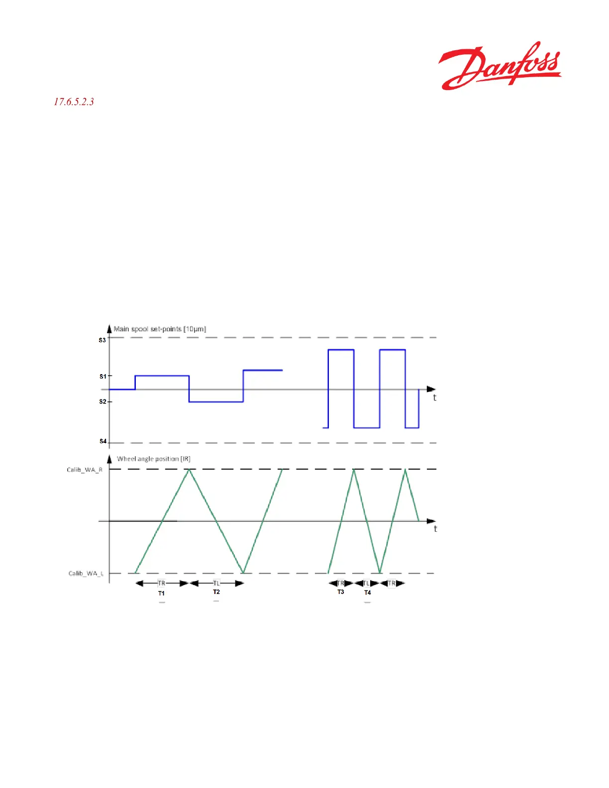
1. The calibration operator inputs two initial experimental main spool set-points S1 and S2 which the calibration
algorithm alternates between.
2. The starting point for the measurement is when the steered wheel angle is at Calib_WA_L.
3. The calibration algorithm applies main spool set-point S1 to initiate a steering direction towards right.
4. The time T1 it takes for the steered wheels to reach Calib_WA_R is measured and denoted TR.
5. When the steered wheels reaches Calib_WA_R, the calibration algorithm applies main spool set-point S2 to
initiate a steering direction towards left.
6. The time T2 it takes for the steered wheels to reach Calib_WA_L is measured and denoted TL.
7. The calibration operator continuously evaluates TR and TL and stepwise increases or decreases the spool set-
points S1 and S2.
8. Repeat from step 3 until TR and TL meets the success criteria described in section 17.6.5.2 and shown as T3
and T4).
Figure 69
 Loading...


